Daikin Clima-Flex CLIC STAND ALONE Series Installation, Operation And Maintenance Manual Download Page 45

iom-clicsa-cf-eng

www.clima-flex.com

45

NAVIGATION KEYS

The 4 navigation keys are used to navigate between the different 

options available in [Quick Menu], [Main Menu] and [Alarm Log]. 

Press the keys to move the cursor.

The [OK] key is used to select a parameter marked by the cursor 

and to enable changing a parameter and logs from the Quick 

Menu.

Local control keys

The keys for local control are located at the bottom of the control 

panel.

Figure 15.  Local control keys

The [Hand On] option allows the frequency converter to be 

controlled by the LCP. The [Hand on] option also starts the motor 

compressor and it is possible to enter the speed data of the motor 

compressor using the arrow keys. 
The key can be selected as [1]

Activate or [0] Deactivate via the [Hand on] key 0-40 on the LCP.

External stop signals activated via control signals or a serial bus 

will override a “start” command via the LCP.

The following control signals will remain active when.[Hand on] 

is activated:

• [Hand On] - [Off] - [Auto On].

• Reset

• Reverse coasting stop

• Reverse

• Select lsb (least significant bit) - [Off] - [Auto On] - [Auto On 

• msb (most significant bit) select msb (most significant bit) 

select msb (most significant bit)

• Stop command from serial communication

• Fast stop

• DC brake

The [Off] key stops the connected motor compressor. The key 

can be selected as [1] Enable or [0] Disable via the 0-41 [Off] key 

in LCP. If no external stop function is selected and the [Off] key is 

inactive, the motor compressor can be stopped by disconnecting 

the voltage.

[Auto On] allows the frequency converter to be controlled via 

the control terminals and/or serial communication. When a start 

signal is applied to the control control terminals and/or the bus, 

the frequency converter will start. The key can be selected as [1] 

Enable or [0] Disable via the 0-42 [Auto on] key on the LCP.

NOTE: An active HAND-OFF-AUTO signal via the digital 

inputs has higher priority than the [Hand on] and 

[Auto on] control keys. 

QUICK TRANSFER OF PARAMETER 

SETTINGS

Once the configuration of a frequency converter has been 

completed, store the data in the LCP or on a PC using the MCT 

10 Set-up Software.

DATA STORAGE IN LCP

1. Go to 0-50 LCP Copy in the main menu.

2. Press [OK].

3. Select [1] All to LCP.

4. Press [OK].

5. All parameter settings are now stored in the LCP indicated by 

the progress bar. When 100% is reached, press [OK].

NOTE: Stop the motor compressor before performing 

this  operation.  The  LCP  can  now  be  connected 

to another frequency converter and copy the 

parameter settings to this frequency converter as 

well.

INITIALIZATION TO DEFAULT 

CONFIGURATION

Initialize the frequency converter to default settings in two ways:

A. 

Recommended initialization (via operating mode 14-22)

• Select operating mode 14-22.

• Press [OK].

• Select [2] Initialization.

• Press [OK].

• Disconnect the mains power and wait until the display turns 

off.

• Reconnect the mains power.

• A80] (Alarm 80) appears - the frequency converter has been 

reset.

14-22 Operating mode Initializes everything except:

• 8-30 Protocol

• 8-31 Address

• 8-32 FC port baud rate

• 8-33 Parity / Stop Bits

• 8-34 Estimated cycle time

• 8-35 Minimum Response Delay

• 8-36 Maximum Response Delay

• 8-37 Maximum Inter-Carriage Delay 8-38 Maximum Inter-

Carriage Delay

• 14-50 RFI filter

• 8-30 Protocol

• 8-31 Address

• 8-32 FC port baud rate

• 8-33 Parity / Stop bits 8-34 Estimated cycle time

• 8-34 Estimated Cycle Time

• 8-35 Minimum Response Delay

• 8-36 Maximum Response Delay

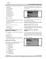
Use [Quick Menu] to program the parameters belonging to the 

Quick Menu. It is possible to switch directly between the Quick 

Menu mode and the Main Menu mode.

Vdf Compressor Controller 

The [Reset] key is used to reset the frequency converter after an 

alarm (trip). It can be selected as [1] Enable or [0] Disable using 

the 0-43 [Reset] key on the LCP.

Direct access to the parameters can be made by holding down 

the [Main Menu] key for 3 seconds. Direct parameter access 

allows direct access to any parameter.

Summary of Contents for Clima-Flex CLIC STAND ALONE Series

Page 1: ...ion and Maintenance Manual CLIC STAND ALONE Series Air Cooled Scroll Compressor Chiller Water Generator Unit Model 25 TR Refrigerant HFC 410A 50 60 Hz IOM Group Chiller Part Number IOM CLIC STAND ALON...

Page 2: ...facility Safety Warning 4 General Description 5 Features Benefits 6 Installation and Application Information 8 Refrigeration Schematics 14 Dimensions and Weights Packaged Units 15 Refrigerant Charge...

Page 3: ...zed at least 12 hours before startup Chiller components EXV Sensors Transducers installed and wired properly Wiring complies with National Electrical Code and local codes See Notes Miscellaneous Yes N...

Page 4: ...ge breaker may result in electric shock or fire WARNING If refrigerant leaks from the unit there is a potential choking danger as the refrigerant will displace air in the immediate area Be sure to fol...

Page 5: ...Only H Heat Pump UNITS 1 Stand alone 2 2 units 3 3 units 4 4 units 5 5 units 6 6 units 7 7 units 8 8 units 9 units 10 10 units CONDENSER FAN A Axial Fixed ANTICORROSION C Coat in Condenser I Coat in...

Page 6: ...ipment comes with a 1 year major warranty after start up Our units use R410A refrigerant which is harmless to the ozone layer and is non toxic and non flammable even in case of leakage Finally the eff...

Page 7: ...water based synthetic coating with ES2 pigment applied to all areas of the coating surface with no bridging of material between fins Therefore ES2 pigments are suitable for even the most corrosive en...

Page 8: ...unit in case of service parts or warranty questions This nameplate also contains the unit s refrigerant charge and electrical ratings The evaporator nameplate is under the insulation and contains the...

Page 9: ...h The foundation must be strong enough to support the weight of the unit see Dimension and Weight Packaged Unit on page 15 The addition of neoprene pads customer supplied under the unit allows water t...

Page 10: ...can be supplied and installed in the field Piping for units with brazed plate evaporators should have a drain and vent connection at the bottom of the bottom connection piping and at the top of the to...

Page 11: ...iately after unit start up NOTE Failure to comply with these measures may result in performance and reliability problems P Vibration Eliminators Isolation Valves Thermometer Thermowell Thermowell Ther...

Page 12: ...controlled by the chiller s microprocessor The controller will activate the pump whenever at least one chiller circuit is enabled for operation This helps ensure proper start up sequence of the unit...

Page 13: ...y may freeze and not indicate a no flow condition HIGH TEMPERATURE OPERATION CLIC STAND ALONE series units for high temperature operation 105 F to 125 F 40 C to 52 C require the addition of the option...

Page 14: ...iom clicsa cf eng www clima flex com 14 Refrigeration Schematics Figure 5 Refrigerant schematics...

Page 15: ...Top View Side View Isometric View Notas 1 25TR Unit Water connections in 6 IN OUT 2101 mm 82 3 4 in 1835 mm 72 1 4 in 784 mm 30 7 8 in 1168 mm 46 in 2215 mm 87 1 4 in 827 mm 32 5 8 in 817 mm 32 1 8 i...

Page 16: ...d pressure drop in clic stand alone unit Refrigerant Charge Pressure Drop REFRIGERANT CHARGE EVAPORATOR PRESSURE DROP FAMILY TR R410A LBS R410A KG GPM PIPE SIZE DP ft WG CLIC 25 1 X 21 1 X 9 5 60 6 34...

Page 17: ...codes including NECA AA 10402012 for installation of aluminum wiring in buildings ANSI Wiring inside the unit is sized in accordance with the NEC Refer to the unit nameplate and unit selection report...

Page 18: ...can cause serious damage to the chiller The procedure required to reconnect generator power to the mains is as follows 1 Set the generator to always run five minutes longer than the unit start timer w...

Page 19: ...8 SHIELED WIRE J3 J9 WHITE WIRE J3 J9 BLACK WIRE NAKED WIRE ON GROUND COMPRESSOR PROTECTOR Located in compressor electrical connection 24vac protector INTERNAL OVERLOAD PROTECTION MC1 MC2 MC3 HPR PHAS...

Page 20: ...S L3 MS L2 MS L1 R 2 C1 5L3 22X NC 31X NC 14X NO 43X NO CAL4 11 CAL4 11 21X NC 32X NC 13X NO 44X NO TF96 MC1 L3 MC1 L2 MC1 L1 Compressor connection EXISTING WIRES DO NOT DISCONECT FAN 1 FAN 2 COMPRESS...

Page 21: ...ATION ONLY IN 2X18 SHIELED WIRE J3 J9 WHITE WIRE J3 J9 BLACK WIRE NAKED WIRE ON GROUND COMPRESSOR PROTECTOR Located in compressor electrical connection 24vac protector INTERNAL OVERLOAD PROTECTION MC1...

Page 22: ...MS L2 MS L1 R 2 C1 5L3 22X NC 31X NC 14X NO 43X NO CAL4 11 CAL4 11 21X NC 32X NC 13X NO 44X NO TF96 MC1 L3 MC1 L2 MC1 L1 Compressor connection EXISTING WIRES DO NOT DISCONECT FAN 1 FAN 2 COMPRESSOR PR...

Page 23: ...anel mounted models or sold separately on DIN rail mounted models CAREL s APPLICA app available on Google Play for the Android operating system makes it easy to configure parameters and commission the...

Page 24: ...chiller on Microchiller On Are there any alarms Is a high pressure alarm present Is a low pressure alarm present Are there alarms for out of range probes Turn on switch ON OFF Hold on start up time Is...

Page 25: ...apacitor approach The capacitor approximation will be calculated for each circuit The equation is as follows Capacitor approximation Capacitor saturated temperature OAT Suction reheating The suction s...

Page 26: ...he operating or pumping state They should not operate when the circuit is in any other state Compressor start up A compressor must start if it receives a start command from the unit capacity control l...

Page 27: ...the bulb to make sure it is properly connected to the suction line If you can move the bulb manually it is not properly secured The bulb must be perfectly insulated to protect it against the effects o...

Page 28: ...imply has a pump configured in this case this alarm goes together with the current pump configuration A15 This alarm usually appears when the water temperature does not drop due to the current cooling...

Page 29: ...the equipment is electrically linked to the pump start which means that when the pump is turned on the fan is turned on however this icon is currently represented on the controller as fan present Whe...

Page 30: ...rm and save the change Press the down key again and the SEtH menu will appear this parameter is used to change the setpoint in HEAT mode only when the units have this option available otherwise it wil...

Page 31: ...OF THE INTERFACE SCREEN OF THE CAREL APPLICATION VIA CELLULAR PHONE The following image shows the interface of the carel application through Bluetooth communication and monitoring of equipment operati...

Page 32: ...ounters 25 1 C007 BOOL R W FALSE C007 Comp 1 circ 2 reset hour counters 26 1 C010 BOOL R W FALSE C010 Comp 2 circ 2 reset hour counters 27 1 C034 BOOL R W FALSE C034 High press switch input logic 0 N...

Page 33: ...FALSE En_SrcRetTempPrb Connected source return temperature probe 90 1 WaitOtherDevCirc1_ SmartOpnExV BOOL R W 0 91 1 LowNoiseActive BOOL R W FALSE Low noise function active 92 1 S073 BOOL R W FALSE S0...

Page 34: ...anual mode steps 100 1 E003 UINT 0 65535 R W 0 STEPS E003 ExV circ 2 manual mode steps 101 2 E004 REAL R W 6 DELTAKELVIN E004 ExV SH set point in cool 103 2 E005 REAL R W 15 E005 ExV SH control Kp in...

Page 35: ...R W 0 S014 Source fan ON OFF circ 2 manual mode 0 AUTO 1 OFF 2 ON 219 1 S015 USINT 0 101 R W 0 PERCENT S015 Source fan inverter circ 2 manual mode 0 AUTO 1 0 2 1 101 100 220 2 S016 REAL R W 5 CELSIUS...

Page 36: ...r pump 1 overload 9 LP pressure switch 10 User pump 2 overload 11 Remote cmd 1 12 Remote cmd 2 13 Source alarm 292 1 Hc07 USINT 0 6 R W 5 Hc07 Digital input 5 con g 0 Not used 1 User ow switch 2 Comp...

Page 37: ...lve on comp starts 353 1 P012 UINT 0 999 R W 3 SECOND P012 Oil equalisation solenoid valve open time 354 1 P013 UINT 0 999 R W 1 MINUTE P013 Oil equalisation solenoid valve min o time 355 1 P014 UINT...

Page 38: ...circ 2 3 User heater step 2 4 User pump 2 5 Source 6 Frost heater 7 4way valve 8 Oil equal valve 748 1 Hc63 USINT 0 8 R W 1 Hc63 Digital output 3 secondary con g 0 Not used 1 Comp 1 circ 2 2 Comp 2 c...

Page 39: ...gue capacity request max value 817 1 U089 USINT 0 2 R W 0 U089 Analogue capacity request input type 0 0 5V 1 0 10V 2 4 20mA 788 1 Hc90 USINT 0 8 R W 0 HC90 Display value selection Large area 789 1 Hc9...

Page 40: ...rce 1 pump maintenance 17 1 A18 BOOL R FALSE Unit Free cooling fault 18 1 A19 BOOL R FALSE Circuit 1 Discharge pressure probe broken or disconnected alarm 19 1 A20 BOOL R FALSE Circuit 1 Condensing te...

Page 41: ...rce 1 pump maintenance 17 1 A18 BOOL R FALSE Unit Free cooling fault 18 1 A19 BOOL R FALSE Circuit 1 Discharge pressure probe broken or disconnected alarm 19 1 A20 BOOL R FALSE Circuit 1 Condensing te...

Page 42: ...1Circ1_DevAlrm Comp 1 circ 1 in alarm condition 93 1 Comp1Circ1_AbleToOn BOOL R FALSE Comp 1 circ 1 enabled to start 94 1 Comp1Circ1_AbleToO BOOL R FALSE Comp 1 circ 1 enabled to stop 95 1 Comp1Circ1_...

Page 43: ...BOOL R FALSE En_SuctTempPrb_Circ1 Connected suction temp probe for circ 1 167 1 UsrHeater2 BOOL R FALSE UsrHeater2 User heater 2 status 168 1 Al_RegulationAlrms BOOL R FALSE Al_RegulationAlrms Control...

Page 44: ...e displayed on the control panel The control panel The power LED is activated when the frequency inverter is supplied with mains voltage Green LED on The control section is running Yellow LED Warning...

Page 45: ...gnal via the digital inputs has higher priority than the Hand on and Auto on control keys QUICK TRANSFER OF PARAMETER SETTINGS Once the configuration of a frequency converter has been completed store...

Page 46: ...p The following parameter groups can be accessed 0 Operation Display 1 Load Motor 3 Reference Ramps 4 Limits Warnings 5 Digital input output 6 Analog input output 7 Controls 8 Communication and option...

Page 47: ...heck for refrigerant leaks Open the unit for hydraulic installation only Do not remove the connection guards until the hydraulic circuit is closed Check for foreign objects in the fan discharge Check...

Page 48: ...quirements and is in automatic mode Check voltage Motor save which is set to supply the correct supply voltage for the unit The percentage of unbalance of the power supply must be calculated with the...

Page 49: ...ence will begin by checking all pre programmed safety points on the unit If all required conditions are correct the unit will be ready to start operations UNIT CONTROL To start operations turn the ON...

Page 50: ...e performed on a regular basis Over long periods of operation the heat exchanger will become fouled impairing efficiency and reducing the units performance Consult your local supplier about cleaning t...

Page 51: ...mended that the unit be turned on 24 hours prior to first start up to begin warming up the compressor crankcase HYDRAULIC MAINTENANCE Jan Feb Mar Apr May Jun Jul Aug Sep Oct Nov Dec Cleaning of the hy...

Page 52: ...Inspection of fan blades cleaning of fan blades Quarterly Plan x x x x Real Compressor power consumption check to determine refrigerant loss quarterly Plan x x x x x x Real Compressor oil inspection m...

Page 53: ...the solenoid Check wiring Motor electrical problems Check for open shorted or bubbled motor Loose wiring Check all wire connections and tighten all terminal screws Compressor makes noise or vibrates C...

Page 54: ...of regulating condenser temperature Excess oil used If the system has excess oil recover and adjust by observing the sight glass on the compressor Motor overload relays or circuit breakers open Volta...

Page 55: ...e Loose fitting in oil line Correct to bring conditions within allowable limits Compressor staging intervals too short Control band not properly adjusted Check and correct Water temperature sensor fai...

Page 56: ...iom clicsa cf eng www clima flex com...

Reviews: