EDUS72-975
Installation Manual
BRC1E71
39
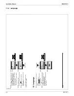
7.5
Power-on
3P243521-2B
12
English
Power-on
5.
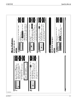
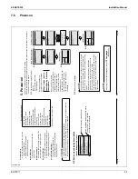
Check for completion of indoor/outdoor unit wiring.
Ɣ
Ensure that covers have been replaced on electrical component boxes for both indoor and outdoor
Ɣ
units prior to restoring power
.
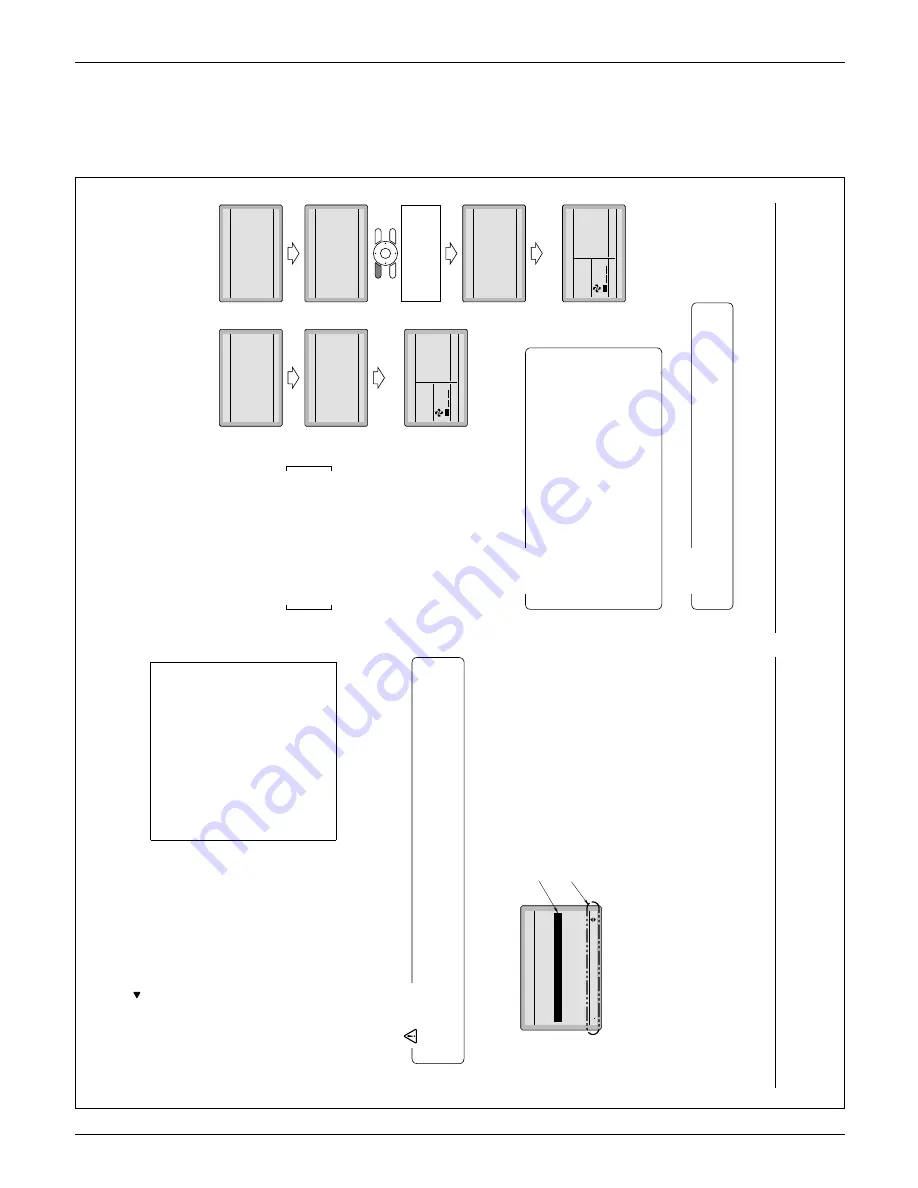
5-1
The following are displayed after
power-on.
“Checking the connection.
Please stand by
.”
During above display
, the
backlight will not be available.
When 1 indoor unit is
controlled by 2 remote
controllers:
Be sure to set sub remote
controller during above display
.
Press and hold 4 seconds or
longer the Operation mode
selector button of the remote
controller to be set.
When the display is changed from
main remote controller to sub
remote controller
, the setting is
completed.
Basic screen is displayed.
5-2
If sub remote controller is not set at power-on in the case
of one indoor unit controlled by two remote controllers,
“Error code: U5” is displayed in the connection checking
screen.
Select the sub remote controller by pressing the
Operation mode selector button of either one of the
remote controllers for 4 seconds or longer
.
If the basic screen is not displayed more than 2 minutes
after “Sub RC” display
, shut of
f the power supply and
check the wiring.
NOTE
When selecting a dif
ferent language, refer to
12
.
Language
.
(See page 21.)
NOTE
<Main remote controller>
<Sub remote controller>
1
5-
Checking the connection.
Please stand by
.
Of
f reminder
T
imer
Main RC
Checking the connection.
Please stand by
.
Error Code U5
Main RC
1
5-
Checking the connection.
Please stand by
.
Of
f reminder
T
imer
Main RC
Checking the connection.
Please stand by
.
Error Code U5
Main RC
Press and hold 4 seconds
or longer the Operation
mode selector button of sub
remote controller side.
Checking the connection.
Please stand by
.
Of
f reminder
T
imer
Sub RC
<Basic screen>
2
5-
Set temperature
28
°C
Fan
Return
Press the menu button
<Basic screen>
2
5-
Set temperature
28
°C
Fan
Return
Press the menu button
01_EN_3P243521-2B.indd 12
8/27/2009 2:00:12 PM
English
11
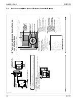
Left button
(7)
Used to highlight items to the left of the
Ɣ
currently selected item.
Display contents are changed to
Ɣ
previous screen per page.
On/Off button
(8)
Press once to operate, and press once
again to stop.
Operation lamp
(9)
Green lamp lights up during operation.
The
lamp will blink if an malfunction occurs.
Cancel button
(10)
Used to return to the previous screen.
Ɣ
Press and hold this button for 4 seconds or
Ɣ
longer to display service settings menu.
LCD (with backlight)
(1
1)
The backlight will illuminate for
approximately 30 seconds by pressing
any operation button.
Service Settings menu
T
est Operation
Maintenance Contact
Field Settings
Energy Saving Options
Prohibit Buttons
Min Setpoints Dif
ferential
Outdoor
unit AirNet Address
Error History
Indoor Unit Status
Outdoor Unit Status
Forced Fan ON
Switch Main Sub Controller
Filter Indicator
Brush/Filter Ind.
Disable Filter
Auto Clean
∗
Depending on connected model
Ɣ
Operate the button while the backlight is illuminated.
When one indoor unit is controlled by two remote controllers (main / sub) only the fi
rst
Ɣ
controller to be accessed by the user will illuminate it’
s backlight.
NOTE
Button menu display descriptions
4-2
Setting
Service Settings
T
e
st Operation
Maintenance Contact
Field Settings
Energy Saving Options
Prohibit Buttons
Min Setpoints Dif
ferential
1/3
In the highlighted display (selected items)
setting screen, button operation
descriptions are displayed.
Highlighted display (selected items)
<Service Settings menu screen>
01_EN_3P243521-2B.indd 11
8/27/2009 2:00:12 PM
Summary of Contents for BRC1E71
Page 1: ...AMERICAS...
Page 8: ...EDUS72 975 Features BRC1E71 7 1 5 Other Features...

