IOM 1242-2 • PATHFINDER
®
MODEL AWV CHILLERS
84 www.DaikinApplied.com
s
TarTup
and
s
huTdown
8. If glycol is not used in the system, drain all water from
the unit evaporator and chilled water piping if the unit is
to be shutdown during winter and temperatures below
-20
°
F can be expected. The evaporator is equipped
with heaters to help protect it down to -20
°
F. Chilled
water piping must be protected with field-installed
protection. Do not leave the vessels or piping open to the
atmosphere over the shutdown period.
9. Do not apply power to the evaporator heaters if the
system is drained of fluids as this can cause the heaters
to burn out.
Startup After Extended (Seasonal)
Shutdown
1. With all electrical disconnects locked and tagged out,
check all screw or lug-type electrical connections to be
sure they are tight for good electrical contact.
DANGER
LOCK AND TAG OUT ALL POWER SOURCES WHEN
CHECKING CONNECTIONS. ELECTRICAL SHOCK WILL
CAUSE SEVERE PERSONAL INJURY OR DEATH.
2. Check the voltage of the unit power supply and see that
it is within the ±10% tolerance that is allowed. Voltage
unbalance between phases must be within ±2%.
3. See that all auxiliary control equipment is operative and
that an adequate cooling load is available for startup.
4.
Check all compressor flange connections for tightness to
avoid refrigerant loss. Always replace valve seal caps.
5. Make sure system switch Q0 is in the “Stop” position and
pumpdown switches Q1 and Q2 are set to “Pumpdown
and Stop”. Throw the main power and control disconnect
switches to “On.” This will energize the crankcase
heaters. Wait a minimum of 12 hours before starting up
unit. Turn compressor circuit breakers to “Off” position
until ready to start unit.
6.
Open the optional compressor suction butterfly valves,
the liquid line shutoff valves, and compressor discharge
valves.
7. Vent the air from the evaporator water side as well as
from the system piping. Open all water flow valves and
start the chilled water pump. Check all piping for leaks
and recheck for air in the system. Verify the correct flow
rate by taking the pressure drop across the evaporator
and compare to the graphs beginning on
page 39
.
8. Set the chilled water set point to the required
temperature. The system water temperature must be
greater than the total of the leaving water temperature
set point plus one-half the control band plus the startup
Delta-T before the MicroTech
®
III controller will stage on
cooling.
9. Under the “Control Mode” menu of the keypad, place the
unit into the automatic Cool Mode.
10. Start the system by moving pumpdown switches to the
“Auto” position.
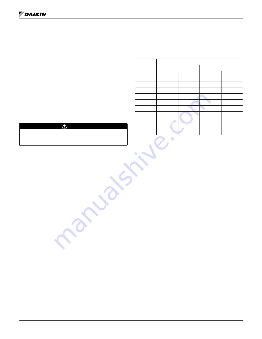
The following table gives glycol concentrations required for
freeze protection.
Table 54: Freeze Protection Temperature
°F (°C)
Percent Volume Glycol Concentration Required
For Freeze Protection
For Burst Protection
Ethylene
Glycol
Propylene
Glycol
Ethylene
Glycol
Propylene
Glycol
20 (6.7)
16
18
11
12
10 (-12.2)
25
29
17
20
0 (-17.8)
33
36
22
24
-10 (-23.3)
39
42
26
28
-20 (-28.9)
44
46
30
30
-30 (-34.4)
48
50
30
33
-40 (-40.0)
52
54
30
35
-50 (-45.6)
56
57
30
35
-60 (-51.1)
60
60
30
35
NOTE:
These values are examples only and cannot be
appropriate to every situation. Generally, for an
extended margin of protection, select a temperature
at least 10
°
F lower than the expected lowest ambient
temperature. Inhibitor levels should be adjusted for
solutions less than 25% glycol.
Glycol of less than 25% concentration is not
recommended, unless inhibitors are adjusted,
because of the potential for bacterial growth and loss
of heat transfer efficiency.
Summary of Contents for AWV008
Page 4: ......


