


6-7
Chapter 6
W
elding Condition
F
UNCTION
ON
O
PERATION
P
ANEL
W
ELDING
C
ONDITION
C
HAPTER
6
15
CRATER-FILL key
Select the crater treatment method or arc spot at the end of welding.
The LED of the parameter in selection lights up.
• For details of the crater treatment (
-
• For details of arc spot (
16
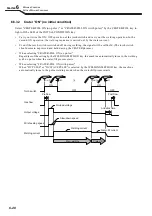
SPOT TIME key
Sets the welding time when "ARC SPOT" is selected by the CRATER-FILL key. (
spot time)
Pressing this key makes the LED lit, enabling to adjust the welding time by the parameter
adjustment knob.
The set time is displayed on the left digital meter.
17
ARC CONTROL key
Set the arc characteristics (soft to hard). (
Arc characteristics adjustment)
Pressing this key makes the LED lit, enabling to adjust the arc characteristics by the
parameter adjustment knob. The arc characteristic in adjustment is displayed on the right
digital meter.
18
INITIAL CONDITION key
When "CRATER-FILL ON" is selected by the CRATER-FILL key, the sequence of initial
condition is added before the welding. (
Pressing this key makes the LED lit, adding the sequence of initial condition.
19
CONSTANT PENETRATION key
Activates the penetration control. (
Penetration control adjustment)
Press this key makes the LED lit, and automatically adjusts the wire feed speed so that
the welding current becomes always constant even with the wire feeding length changed.
This function is available only when the "MILD STEEL CORED", "MILD FLUX CORED", "SUS
SOLID" or "SUS FLUX CORED" is selected by the WIRE MATERIALS key.
20
WAVE FRQ key
Sets the wave frequency when "DC WAVE PULSE" is selected by the WELDING METHOD
key. (
Pressing this key lights the LED, enabling to adjust the wave frequency by the parameter
adjustment knob.
The set wave frequency is displayed on the left digital meter.
21
TORCH key
Select air-cooled welding torch or water-cooled welding torch to be used. Switching the
mode is enabled by pressing the key.
• When the LED is ON: water-cooled welding torch mode
• When the LED is OFF: air-cooled welding torch mode
22
VOLT.ADJUST key
Sets welding voltage. Switching the mode is enabled by pressing the key.
• When the LED of the VOLT. ADJUST key is on: SYNERGIC mode. (The welding voltage
is automatically set according to the set welding current. To fine-tune welding voltage,
adjust the synergic fine adjustment knob.)
• When the LED of the VOLT. ADJUST key is off: INDIVIDUAL mode. (In the individual
adjustment setting, welding current and welding voltage are adjusted respectively.)
23
WELD MONITOR key
Sets welding control function. (See Chapter 7 Administrator Functions.)
Pressing this key for a second or more lights up the LED, and the sequence transits to the
welding control mode.
24
LOAD key
Reads the registered welding condition from the internal memory. (
-
Function of Welding Conditions)
25
SAVE key
Registers the set welding condition in the internal memory. (
26
ENTER key
Carries out the administrative functions such as key lock, password, and registration of
welding condition to the memory.
Depressing the key for three seconds or more makes the LED lit, enabling the key lock
function.
27
WARNING/Temperature LED
Lights up or flashes when any failure or abnormal condition occurs in the welding power
source. (
28
USB connector
For variety of registered data, writes to or reads from the USB memory. (
Chapter 7
29
Terminals for service use
Terminals for the OTC service use.
*1: Selective options can be optionally available (OP).
*2: When you select option, item is added.
No.
Name
Function