background image

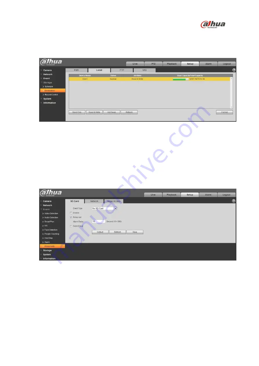
2. Select the recording medium for each event Recorded and Snapshot event, Scheduled, Motion 

Detect and Alarm. Select the Local check box to record an event to the Micro SD card.

3. Click the Local tab to view the used capacity and the total capacity of the Micro SD card.

Figure 5-12

4. Expand the Event menu, located at the left of the Web interface, then select the Abnormality page

to set alarms related to the Micro SD card. The contains the following Micro SD card alarm 
options:

No SD Card: Device triggers an alarm if the device does not contain a Micro SD card.

Capacity Warning: Device triggers an alarm when the data on the Micro SD card passes a 
defined threshold.

SD Card Error: Device triggers an alarm if it detects an issues writing data or retrieving data 
from the Micro SD card.

Figure 5-13

5. Select the event from the Event Type pull-down menu (No SD Card, Capacity Warning, SD Card 

Error).

6. Check the Enable box to activate the alarm for this event.
7. Check the Relay-out box to enable a relay alarm. Then, specify the time in seconds to delay the 

alarm relay output (10 s to 300 s).

23

Summary of Contents for 50430UN

Page 1: ...4 MP PTZ Network Camera 50430UN 59430UN Quick Start Guide Version 001 001 Dahua Technology USA Inc ...

Page 2: ...tion and Configuration 7 3 1 Camera Configuration and Cables 7 3 2 Framework and Dimensions 8 3 3 Alarm Setup 8 Alarm Input 8 Alarm Output Level Application 9 Alarm Output Switch Application 9 3 4 Locally Storing Data 10 4 Device Installation 11 4 1 Installing the Camera 11 5 Network Configuration 14 5 1 Network Protocols 14 5 2 Modifying the IP Address 15 5 3 Using the ConfigTool 15 5 4 Accessing...

Page 3: ...protect the unit from damage especially in damp environments Protect the plug and power cord from foot traffic being pinched and its exit from the unit Units with or without an ON OFF switch have power supplied to the unit whenever the power cord is inserted into the power source however the unit is operational only when the ON OFF switch is in the ON position The power cord is the main power disc...

Page 4: ...ng or installation Environmental Precautions Do not aim the unit at a strong light source or into direct sunlight to focus A strong light source may cause overexposure and may affect the longevity of the CCD or the CMOS sensor Transport use and store the unit within the specified temperature and humidity range Do not place the unit in a wet dusty extremely hot or an extremely cold environment and ...

Page 5: ...wipe a dome cover during installation this cover is an optical device Refer to the following methods clean the dome cover Stained with dirt Use an oil free soft brush or blower to gently remove the dirt Stained with grease or fingerprints Use a soft cloth to wipe gently the water droplet or the oil from the dome cover Then use an oil free cotton cloth or paper soaked with alcohol or detergent to c...

Page 6: ...e that interference will not occur in a particular installation If this equipment does cause harmful interference to radio or television reception which can be determined by turning the equipment off and on the user is encouraged to try to correct the interference by one or more of the following measures Reorient or relocate the receiving antenna Increase the separation between the equipment and r...

Page 7: ... information Dahua accepts no liability for damage resulting directly or indirectly from faults incompleteness or discrepancies between this guide and the product described Dahua is not liable for any loss caused by installation operation or maintenance inconsistent with the information in this guide Video loss is inherent to all digital surveillance and recording devices therefore Dahua cannot be...

Page 8: ... service Retain the carton and all shipping material for future use Please refer to the enclosed CD for more details to view the detailed User s Manual and for configuration software 2 1 Parts List Package Item Quantity Network PTZ Camera 1 Quality Tag 1 Pair of Gloves 1 Installation Hardware Pack 1 Expansion Bolts 3 Screws 3 Hex Key 1 Wall Mount Accessory Kit 1 Wall Mount Adapter 1 Wall Mount Ada...

Page 9: ...nstallation and Configuration 3 1 Framework and Dimensions The following figures show the dimensions of the device in mm in These images are intended as a reference only Figure 3 1 Dimensions for 50430UN 7 ...

Page 10: ... 59430UN 3 2 Wiring The dome camera includes the following wiring bundles Wire Color Connection Power Red 24 VAC Yellow Green Earth Ground Black 24 VAC Video Control Black RJ 45 Ethernet Alarm Red Alarm IN 1 Brown Alarm IN 2 8 ...

Page 11: ... connected to the 3 3 V or it is idle then the device receives the alarm input signal If input signal is grounded then no alarm input signal is detected Figure 3 3 Alarm Output Level Application Use this alarm output configuration if the output triggers an external device by increasing the voltage The alarm must increase the external pull up resistance to trigger high level the device The maximum ...

Page 12: ...valent substitute as these cards have been fully tested without issue and the SanDisk Extreme line is better suited for constant recording Lower grade SD cards meant for multimedia applications will at times have questionable quality and reliability Recording to the SD card is first in first out FIFO The camera deletes the oldest first entry as new storage requirements arise The camera does not si...

Page 13: ...ll other countries Branch circuit protection incorporating a 20 A 2 pole Listed Circuit Breaker or Branch Rated Fuses are required as part of the building installation A readily accessible 2 pole disconnect device with a contact separation of at least 3 mm must be incorporated 24 VAC Class 2 power supply only 4 1 Preparing the Camera 1 Remove the camera the mount accessories and any hardware packa...

Page 14: ...ion bolts using a drill bit that is no wider than the expansion bolt 3 Drill a 50 mm approximately 2 in center hole to route the cables if necessary 4 Insert an expansion bolt into each pre drilled perimeter hole 5 Secure the Junction Box or the Power Supply Box to the wall using four hex bolts and four flat washers if using Do not secure the Wall Mount PFB300S to the wall at this step 6 Screw the...

Page 15: ...all b Use four 4 hex screws and four 4 flat washers to secure the PFB 300S Wall Mount to the PFA 120 Junction Box or to the wall 10 If using the PFA 140 Power Supply Box a Route the cables from the rear of the wall mount and through the hole in the cover of the power supply box b Use four 4 hex screws and four 4 flat washers to secure the PFB300S Wall Mount to the PFA140 Power Supply Box c Attach ...

Page 16: ... cable 15 Supply power to the camera 16 Ensure the safety tether is attached to camera pedestal and to the dome cover 4 3 Mounting the Camera to a Pole The dome camera can be mounted to a pole or mast with the optional PFA 150 Pole Mount Adapter This adapter uses three metal straps to secure the camera to a pole with a diameter of 80 mm to 130 mm 3 18 in to 5 12 in Use the following accessories to...

Page 17: ...re and then fix the set screw on the Wall Mount 6 Pull the composite cable from the dome through the adapter block and pull it out of the other end of the wall mount bracket 7 Line up the hook at the top of the external enclosure to the inside hole of the adapter block and then push it to the end and then tighten the three M6 screws on the adapter block firmly Note Ensure the M6 screws are tightly...

Page 18: ...onnection plate and then through the center hole of the connection plate 3 Place the connection plate against the ceiling and mark the location of the center hole and the four perimeter mounting holes 4 Pre drill the four perimeter holes as marked on the ceiling for the bolts using a drill bit that is no wider than the expansion bolt 5 Drill a 50 mm approximately 2 in center hole to route the cabl...

Page 19: ... the decorative cover towards the ceiling to cover the connection plate 11 Wrap several turns of Teflon tape around the threads of the PFA110 Mount Adapter Block 12 Screw the PFA 110 Mount Adapter Block into the internal thread of the PFB300C Ceiling Mount until secure and then fix the set screw on the PFB300C Ceiling Mount 13 Make wire connections to composite cable and then carefully push the ca...

Page 20: ... external enclosure to the inside hole of the adapter block and then push it to the end and then tighten the three M6 screws on the adapter block firmly Note Ensure the M6 screws are tightly fixed to secure the dome to the ceiling mount 18 ...

Page 21: ...d automate the assignment of IP addresses DHCP should only be enabled if using dynamic IP address notification or if the DHCP can update a DNS server TFTP The Trivial File Transfer Protocol is a simple lock step File Transfer Protocol which allows a client to get from or put a file onto a remote host TFTP lacks security and most of the advanced features offered by more robust file transfer protoco...

Page 22: ...ool to access and to modify the network settings of a device Refer to the Operation Manual available on the CD included with the camera or on Dahuasecurity com for complete information Notes Ensure that the network parameters of each camera is available before starting configuration The ConfigTool supports those cameras that are part of the same network that as the computer running the ConfigTool ...

Page 23: ...ave different Web interfaces the figures below are for reference only and may not represent the Web Interface for your camera Refer to the Web Operation Manual included on the CD shipped with the camera for more details 1 Launch Internet Explorer and type the modified camera IP address in the address bar Internet Explorer opens the Login page 22 Type the Username and Password for the camera The de...

Page 24: ... Normally Closed NC 3 Check the Relay Out box to enable the alarm activation function 4 Select an alarm output port to activate a corresponding alarm device when an alarm occurs Check Send Email to have the device send an email to alert when alarm occurs and ends Check Snapshot to have the device automatically take a snapshot of the scene if alarm occurs 5 6 Configuring Local SD Card Recording The...

Page 25: ...llowing Micro SD card alarm options No SD Card Device triggers an alarm if the device does not contain a Micro SD card Capacity Warning Device triggers an alarm when the data on the Micro SD card passes a defined threshold SD Card Error Device triggers an alarm if it detects an issues writing data or retrieving data from the Micro SD card Figure 5 13 5 Select the event from the Event Type pull dow...

Page 26: ... a specified user after the device triggers an alarm 9 Set the capacity limit for the Micro SD Card available with the Capacity Warning event type The device triggers an alarm once the amount of data on the card surpasses this limit Figure 5 14 24 ...

Page 27: ...gy USA Inc 23 Hubble Irvine CA 92618 Tel 949 679 7777 Fax 949 679 5760 Email sales usa global dahuatech com Rev 001 001 2017 Dahua All rights reserved Design and specifications are subject to change without notice 25 ...

Reviews: