


7.Electrical Interface
© China Daheng Group, Inc. Beijing Image Vision Technology Branch 28
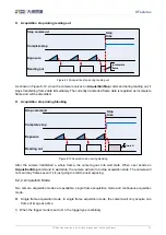
3.3V
Line2
INPUT2
9
1
2
3
4
5
6
7
8
12
11
10
Input-
Input+
External
circuit
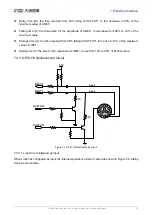
Figure 7-8 Internal equivalent circuit of camera when Line2 is configured as input
To avoid the damage of GPIO pins, please connect GND pin before supplying power to Line2/3.
Logic 0 input voltage: 0V~+0.6V(Line2/3 voltage)
Logic 1 input voltage: +1.9V~+24V(Line2/3 voltage)
The status is unstable when input voltage is between 0.6V and 1.9V, which should be avoided
When input of Line2/3 is high, input current is lower than 100uA. When input of Line2/3 is low, input
current is lower than -1mA
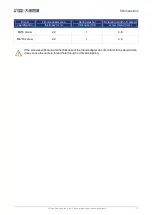
When Line2/3 is configured as input. The connection method between them and NPN and PNP
photoelectric sensors is shown in Figure 7-9 and Figure 7-10. The relationship between the pull-up resistor
value and the external input voltage is shown in Table 7-3.


