


8.Features
© China Daheng Group, Inc. Beijing Image Vision Technology Branch 45
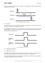
The camera's trigger source Line0 uses opto-isolated circuit to isolate signal. Its internal circuit
delay trigger signal and rising edge's delay time is less than falling edge's. There are a dozen clock
cycles delay of rising edge and dozens clock cycles delay of falling edge. If you use Line0 to trigger
the camera, the positive pulse signal's positive width will be wider (about 20-40
μs
) and the
negative pulse signal's negative width will be narrower (about 20-40
μs
). You can adjust filter
parameter to accurately filter trigger signal.
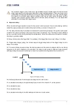
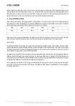
Exposure delay
When an external trigger signal is received to the sensor to start exposure, there is a small delay, which is
called the exposure delay and consists of four parts of time, as shown in Figure 8-19.
T1: The delay introduced by the hardware circuit when the external signal passes through the optocoupler
or GPIO. The value is generally in the range of several
to several tens of μs. The delay is mainly affecte
d
by the connection mode, driving intensity and temperature. When the external environment is constant,
the delay is generally stable.
T2: Delay introduced by the trigger filter. For example, if the trigger filter time is set to 50μs, T2 is 50μs.
T3: Trigger delay (trigger_delay), the camera supports trigger delay feature. If the trigger delay is set to
200μs, T3 is 200μs.
T4: The sensor timing sequence delay, the internal exposure of the sensor is aligned with the row timing
sequence, so T4 has a maximum row cycle jitter. The value of each sensor is different. Some products
with large delay time (several hundred
μs
or more) have additional configuration time counted in T4.
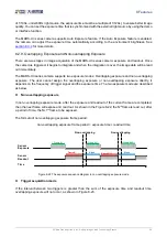
Total exposure delay
Line0/2/3
T1
T2
T3
T4
Exposure start
Image readout
Figure 8-19 Exposure delay
The following table shows the total exposure delay time for each sensor.
T1 is calculated according to the typical delay (5μs) of line0. If it is line2/3, T1 can be ignored.
T2 is calculated as
0μs.
T3 is calculated as
0μs.
T4 is calculated according to the ROI settings and features of each sensor.


