S0302000
Page 8
General Maintenance Procedures
scratching. Curling under of any seal lip will seriously impair its efficiency. Apply a thin coat of Loctite
#120 to outer diameter, of metal casing, on oil seals to assure an oil tight fit into retainer. Use extreme
care not to get Loctite on lips of oil seals. If this happens, that portion of the seal will become brittle
and allow leakage.
When replacing lip type seals, make sure spring loaded side is towards oil to be sealed.
5.
If available, use magna-flux or similar process for checking for cracks that are not visible to the eye.
Examine teeth on all gears carefully for wear, pitting, chipping, nicks, cracks or scores. Replace all
gears showing cracks or spots where case hardening has worn through. Small nicks may be
removed with suitable hone. Inspect shafts and quills to make certain they have not been sprung,
bent, or splines twisted, and that shafts are true.
NOTE:
Spline wear is not considered detrimental except where it affects tightness of splined
parts.
Inspect thrust washers for distortion, scores, burs, and wear. Replace thrust washer if defective or
worn.
6.
Inspect bores and bearing surfaces of cast parts and machined surfaces for scratches, wear, grooves
and dirt. Remove any scratches and burrs with crocus cloth. Remove foreign material. Replace any
parts that are deeply grooved or scratched which would affect their operation.
BEARING INSPECTION
The conditions of the bearing are vital to the smooth and efficient operation of the machinery. When any
component containing bearings is disassembled, always carefully examine the condition of the bearings
and all of its components for wear and damage.
Once the bearing is removed, clean all parts thoroughly using a suitable cleaning solution. If the bearing is
excessively dirty soak the bearing assembly in a light solution and move the bearing around until all
lubricants and or foreign materials are dissolved and the parts are thoroughly clean.
When drying bearings, moisture free compressed air can be used. Be careful not to direct the air in a
direction which will force the bearing to dry spin while not being properly lubricated.
After the bearings have been cleaned and dried, carefully inspect all bearing rollers, cages and cups for
wear, chipping or nicks. If the bearing cannot be removed and is to be inspected in place, check foe
roughness of rotation, scoring, pitting, cracked or chipped races. If any of these defects are found replace
the whole bearing assembly. NEVER replace the bearing alone without replacing the mating cup or the
cone at the same time.
After inspection lightly coat the bearing and related parts with oil and wrap in a clean lintless cloth or paper
and protect them from moisture and other foreign materials until installation.
It is also important to inspect the bearing housing and/or shaft for grooved, galled or burred conditions that
indicate that the bearing has been turning in its housing or on its shaft.
If available, use magna-flux or similar process for checking for cracks that are not visible to the naked eye.
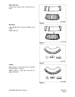
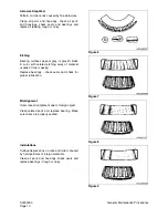
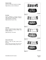
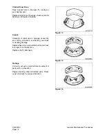
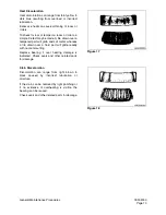
The following illustrations will aid in identifying and diagnosing some of the bearing related problems.
NOTE:
The illustrations will only show tapered roller bearings, but the principles of identifying,
diagnosing and remedying the defects are common to all styles and types of bearings.
Summary of Contents for Solar 225LC-V
Page 2: ......
Page 4: ......
Page 7: ...1SAFETY ...
Page 8: ......
Page 46: ...S0102000 Page 38 Track Excavator Safety ...
Page 47: ...1SPECIFICATIONS ...
Page 48: ......
Page 54: ...S0205015K Page 6 Specifications for Solar 225LC V Return to Master Table of Contents ...
Page 70: ...S0205015K Page 22 Specifications for Solar 225LC V Return to Master Table of Contents ...
Page 71: ...1GENERAL MAINTENANCE ...
Page 72: ......
Page 86: ...S0302000 Page 14 General Maintenance Procedures ...
Page 99: ...1UPPER STRUCTURE ...
Page 100: ......
Page 102: ...S0402040K Page 2 Cab TABLE OF CONTENTS Removal 3 Installation 6 ...
Page 116: ...S0403050K Page 8 Counterweight Return to Master Table of Contents ...
Page 140: ...S0407000 Page 6 Swing Bearing ...
Page 165: ...1LOWER STRUCTURE AND CHASSIS ...
Page 166: ......
Page 192: ...S0505030 Page 26 Track Assembly Return to Master Table of Contents ...
Page 193: ...1ENGINE AND DRIVE TRAIN ...
Page 194: ......
Page 205: ...S0605060K Page 11 Air Conditioner Face and Defroster ARS1300L Figure 12 ...
Page 229: ...S0609000 Page 9 Drive Coupling Main Pump Figure 10 DRIVE COUPLING INSTALLATION UCHIDA PUMP ...
Page 234: ...S0609000 Page 14 Drive Coupling Main Pump ...
Page 235: ...1HYDRAULICS ...
Page 236: ......
Page 249: ...S0702170K Page 13 Hydraulic System Troubleshooting Testing and Adjustment ...
Page 272: ...S0702170K Page 36 Hydraulic System Troubleshooting Testing and Adjustment ...
Page 274: ...S0703010K Page 2 Accumulator TABLE OF CONTENTS General Description 3 Specifications 4 ...
Page 297: ...S0705000 Page 9 Cylinders ...
Page 301: ...S0705000 Page 13 Cylinders ...
Page 311: ...S0705000 Page 23 Cylinders ...
Page 315: ...S0705000 Page 27 Cylinders ...
Page 324: ...S0705000 Page 36 Cylinders 17 Force out pin bushing 1 from body of cylinder Figure 28 ...
Page 328: ...S0705000 Page 40 Cylinders ...
Page 335: ...S0707200 Page 7 Swing Motor Return to Master Table of Contents ...
Page 341: ...S0707200 Page 13 Swing Motor Return to Master Table of Contents SPECIAL TOOLS Figure 6 ...
Page 358: ...S0707200 Page 30 Swing Motor Return to Master Table of Contents ...
Page 452: ...S0708320 Page 40 Main Pump With Regulator Return to Master Table of Contents ...
Page 458: ...S0709401K Page 6 Main Control Valve Kayaba Figure 1 ...
Page 459: ...S0709401K Page 7 Main Control Valve Kayaba Figure 2 ...
Page 461: ...S0709401K Page 9 Main Control Valve Kayaba ...
Page 463: ...S0709401K Page 11 Main Control Valve Kayaba Figure 4 ...
Page 475: ...S0709401K Page 23 Main Control Valve Kayaba Figure 16 ...
Page 508: ...S0709401K Page 56 Main Control Valve Kayaba Figure 54 ...
Page 563: ...1ELECTRICAL SYSTEM ...
Page 564: ......
Page 618: ...S0802220K Page 54 Electrical System ...
Page 637: ...S0802220K Page 73 Electrical System ...
Page 649: ...1ATTACHMENTS ...
Page 650: ......
Page 670: ......

