S0407000
Page 3
Swing Bearing
SWING BEARING MAINTENANCE
OPERATING RECOMMENDATION
The service life of the swing bearing may be extended if a conscious, daily effort is made to equalize usage
over both ends of the excavator. If the excavator is used in the same operating configuration day in and
day out (for example, with the travel motors always under the counterweight, or with the attachment over
one side of the machine more than the other), the bearing’s service life could be reduced. Taking a few
minutes in the middle of each work shift to reposition the excavator, to work the opposite end of the
bearing, will provide a payoff in terms of more even, gradual rate of wear and extended service life.
MEASURING SWING BEARING AXIAL PLAY
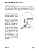
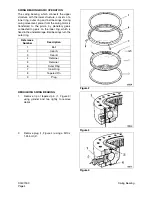
Periodic, regular checks of bearing
displacement should be made at least twice a
year. Use a dial indicator. Push the attachment
against the ground to lift the excavator off the
ground and take measurements at 4 points, 90°
apart, around the circumference of the bearing
(Figure 1).
Record and keep all measurements. Play in the
bearing should increase minimally from one
inspection to the next. Eventually, however, as
the bearing begins to approach the limit of its
service life, clearance increases become much
more pronounced and the actual measured play
in the bearing could exceed twice the value that
was measured when the machine was new.
MEASURING BEARING LATERAL PLAY
When vertical checks are made, the side-to-side
play in the bearing can be checked by fully
retracting the arm and bucket cylinders and
extending the tip of the bucket as far forward as
it will go. With the excavator parked on a flat,
level surface and the bucket tip just off the
ground, push against the bucket sideways to
take up all of the lateral clearance in the
bearing. (Less than 100 lb of force should be
required to move the bucket over all the way.)
Check lateral play in both directions and record
the values. When the bearing is beginning to
approach the end of its service life, measured
lateral clearance should start to show larger and
larger increases.
Figure 1
Summary of Contents for Solar 225LC-V
Page 2: ......
Page 4: ......
Page 7: ...1SAFETY ...
Page 8: ......
Page 46: ...S0102000 Page 38 Track Excavator Safety ...
Page 47: ...1SPECIFICATIONS ...
Page 48: ......
Page 54: ...S0205015K Page 6 Specifications for Solar 225LC V Return to Master Table of Contents ...
Page 70: ...S0205015K Page 22 Specifications for Solar 225LC V Return to Master Table of Contents ...
Page 71: ...1GENERAL MAINTENANCE ...
Page 72: ......
Page 86: ...S0302000 Page 14 General Maintenance Procedures ...
Page 99: ...1UPPER STRUCTURE ...
Page 100: ......
Page 102: ...S0402040K Page 2 Cab TABLE OF CONTENTS Removal 3 Installation 6 ...
Page 116: ...S0403050K Page 8 Counterweight Return to Master Table of Contents ...
Page 140: ...S0407000 Page 6 Swing Bearing ...
Page 165: ...1LOWER STRUCTURE AND CHASSIS ...
Page 166: ......
Page 192: ...S0505030 Page 26 Track Assembly Return to Master Table of Contents ...
Page 193: ...1ENGINE AND DRIVE TRAIN ...
Page 194: ......
Page 205: ...S0605060K Page 11 Air Conditioner Face and Defroster ARS1300L Figure 12 ...
Page 229: ...S0609000 Page 9 Drive Coupling Main Pump Figure 10 DRIVE COUPLING INSTALLATION UCHIDA PUMP ...
Page 234: ...S0609000 Page 14 Drive Coupling Main Pump ...
Page 235: ...1HYDRAULICS ...
Page 236: ......
Page 249: ...S0702170K Page 13 Hydraulic System Troubleshooting Testing and Adjustment ...
Page 272: ...S0702170K Page 36 Hydraulic System Troubleshooting Testing and Adjustment ...
Page 274: ...S0703010K Page 2 Accumulator TABLE OF CONTENTS General Description 3 Specifications 4 ...
Page 297: ...S0705000 Page 9 Cylinders ...
Page 301: ...S0705000 Page 13 Cylinders ...
Page 311: ...S0705000 Page 23 Cylinders ...
Page 315: ...S0705000 Page 27 Cylinders ...
Page 324: ...S0705000 Page 36 Cylinders 17 Force out pin bushing 1 from body of cylinder Figure 28 ...
Page 328: ...S0705000 Page 40 Cylinders ...
Page 335: ...S0707200 Page 7 Swing Motor Return to Master Table of Contents ...
Page 341: ...S0707200 Page 13 Swing Motor Return to Master Table of Contents SPECIAL TOOLS Figure 6 ...
Page 358: ...S0707200 Page 30 Swing Motor Return to Master Table of Contents ...
Page 452: ...S0708320 Page 40 Main Pump With Regulator Return to Master Table of Contents ...
Page 458: ...S0709401K Page 6 Main Control Valve Kayaba Figure 1 ...
Page 459: ...S0709401K Page 7 Main Control Valve Kayaba Figure 2 ...
Page 461: ...S0709401K Page 9 Main Control Valve Kayaba ...
Page 463: ...S0709401K Page 11 Main Control Valve Kayaba Figure 4 ...
Page 475: ...S0709401K Page 23 Main Control Valve Kayaba Figure 16 ...
Page 508: ...S0709401K Page 56 Main Control Valve Kayaba Figure 54 ...
Page 563: ...1ELECTRICAL SYSTEM ...
Page 564: ......
Page 618: ...S0802220K Page 54 Electrical System ...
Page 637: ...S0802220K Page 73 Electrical System ...
Page 649: ...1ATTACHMENTS ...
Page 650: ......
Page 670: ......

