-11-
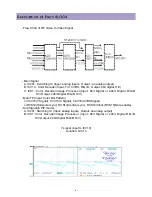
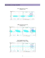
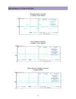
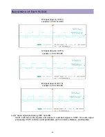
Horizontal sync (Out of ICS1)
Location: RCS12, ICD10.72PIN
Vertical sync (Out of ICS1)
Location: RCS13, ICD10.71PIN
Clock for display (Out of ICS1)
Location: RCS14, ICD10.76PIN
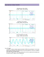
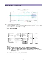
4-2-2. TV signal
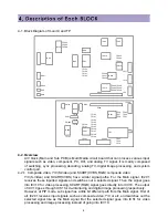
Tuner(TU1) receives antenna signal and outputs CVBS and sound signal. For the main
signal, IC201 switches out the CVBS and the rest of the signal flow is same as composite
video signal flow mentioned earlier.
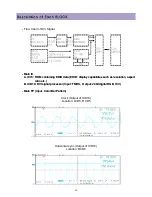
Also, Sub TV signal at PIP mode flows similar path to the Sub composite video signal pass
except that IC201 switches out the CVBS signal
Summary of Contents for DLP-2612
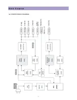
Page 7: ...7 3 2 POWER BLOCK DIAGRAM...
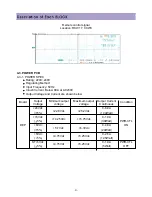
Page 34: ...34 G Signal LCA4 B Signal LCA5 Clock RCA10 near ICA10...
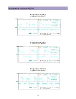
Page 36: ...36 Horizontal sync RCD6 near ICD10 Vertical sync RCD7 near ICD10...
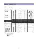
Page 45: ...45 COMPONENT PICTURE REMARK 1 LCD MODULE 2 MAIN BOARD 3 SUB BOARD 4 POWER BOARD...
Page 46: ...46 COMPONENT PICTURE REMARK 5 RONT MASK 6 BACK COVER 7 STAND 8 ALL CONNECTROR CONNECTION...
Page 60: ...11 SCHEMATIC DIAGRAM 62...
Page 61: ...SCHEMATIC DIAGRAM 63...
Page 62: ...SCHEMATIC DIAGRAM 64...
Page 63: ...SCHEMATIC DIAGRAM 65...
Page 64: ...SCHEMATIC DIAGRAM 66...
Page 65: ...SCHEMATIC DIAGRAM 67...
Page 66: ...SCHEMATIC DIAGRAM 68...
Page 67: ...SCHEMATIC DIAGRAM 69...
Page 68: ...SCHEMATIC DIAGRAM 70...
Page 69: ...SCHEMATIC DIAGRAM 71...
Page 70: ...SCHEMATIC DIAGRAM 72...
Page 71: ...SCHEMATIC DIAGRAM 73...
Page 72: ...SCHEMATIC DIAGRAM 74...
Page 73: ...SCHEMATIC DIAGRAM 75...
Page 74: ...SCHEMATIC DIAGRAM 76...
Page 75: ...77 10 1 DLP 3212APSB...
Page 76: ...78 10 2 DLP 2612APSB...


