-37-
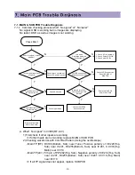
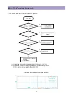
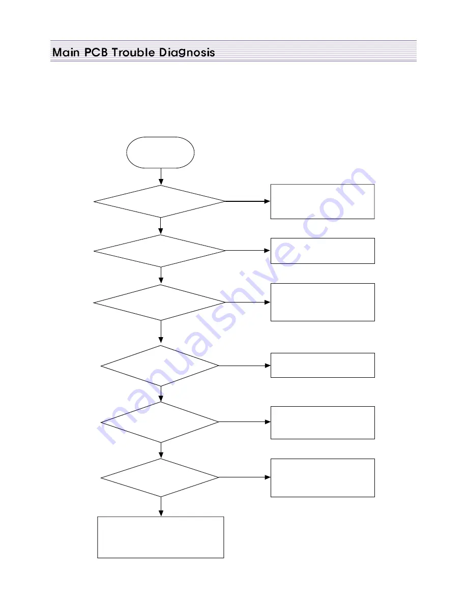
7-1-2. When No Sound
A. Overview
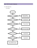
Check Start
Do images display on screen?
Cancel Sound MUTE
Check the connection of Jack
(LCD and AV device)
Check the connection of Speaker
Perhaps IC601 Problem
Replace SUB PCB
IC603 & IC604 Problem
Replace Sub PCB
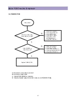
1. Check AC connection
2. Check Power S/W ON
3. Check Main or other PCBs
Check Sound Mute Off?
Y
Y
Y
Y
Y
Y
N
N
N
N
N
N
Is the Sound input Jack
properly connected?
Is the Speaker connection
Correctly connected?
Check 11th PIN of IC603
and IC604?
Check Sound output at
P601 and PW602?
Problem of SPEAKER or Sound Cable.
Replace SPEAKER of Sound Cable.
Summary of Contents for DLP-2612
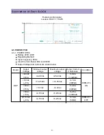
Page 7: ...7 3 2 POWER BLOCK DIAGRAM...
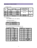
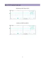
Page 34: ...34 G Signal LCA4 B Signal LCA5 Clock RCA10 near ICA10...
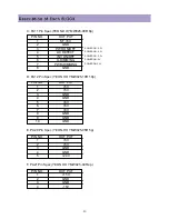
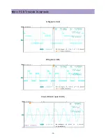
Page 36: ...36 Horizontal sync RCD6 near ICD10 Vertical sync RCD7 near ICD10...
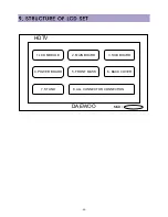
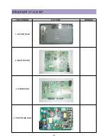
Page 45: ...45 COMPONENT PICTURE REMARK 1 LCD MODULE 2 MAIN BOARD 3 SUB BOARD 4 POWER BOARD...
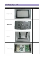
Page 46: ...46 COMPONENT PICTURE REMARK 5 RONT MASK 6 BACK COVER 7 STAND 8 ALL CONNECTROR CONNECTION...
Page 60: ...11 SCHEMATIC DIAGRAM 62...
Page 61: ...SCHEMATIC DIAGRAM 63...
Page 62: ...SCHEMATIC DIAGRAM 64...
Page 63: ...SCHEMATIC DIAGRAM 65...
Page 64: ...SCHEMATIC DIAGRAM 66...
Page 65: ...SCHEMATIC DIAGRAM 67...
Page 66: ...SCHEMATIC DIAGRAM 68...
Page 67: ...SCHEMATIC DIAGRAM 69...
Page 68: ...SCHEMATIC DIAGRAM 70...
Page 69: ...SCHEMATIC DIAGRAM 71...
Page 70: ...SCHEMATIC DIAGRAM 72...
Page 71: ...SCHEMATIC DIAGRAM 73...
Page 72: ...SCHEMATIC DIAGRAM 74...
Page 73: ...SCHEMATIC DIAGRAM 75...
Page 74: ...SCHEMATIC DIAGRAM 76...
Page 75: ...77 10 1 DLP 3212APSB...
Page 76: ...78 10 2 DLP 2612APSB...

