background image

6.4.4. Precautions for operation

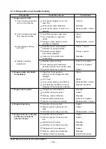
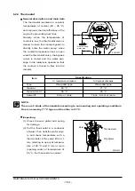
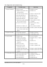
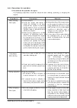
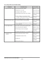
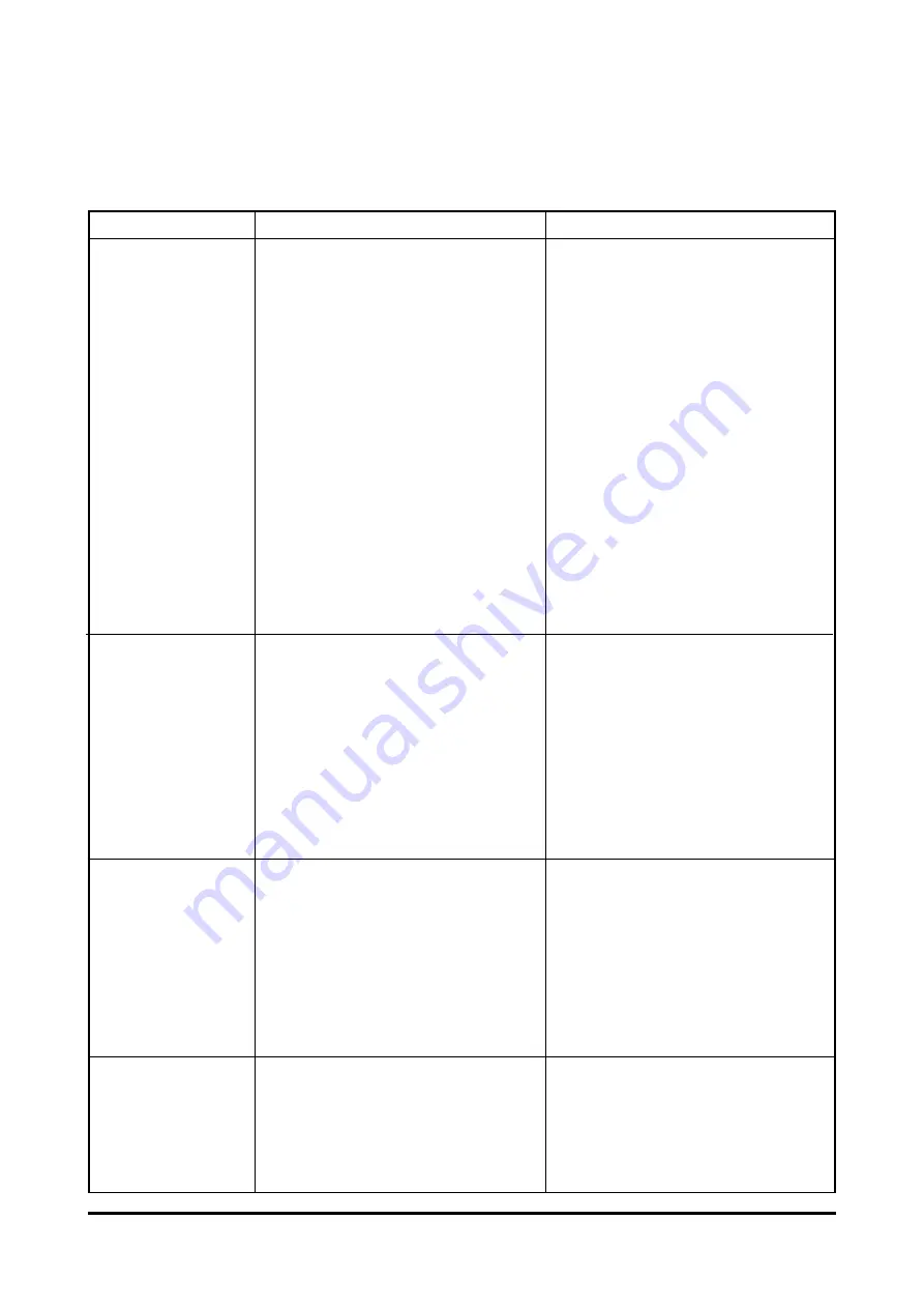
1) Precautions for operation of engine

The following precautions should be observed when starting, operating, or stopping the

engine :

- 164 -

MAINTENANCE OF MAJOR COMPONENTS

Operations

Precautions

Reasons

When starting

the engine

1) Check oil level

2) Crank the engine with starter to

check the increase in oil pres-

sure(until the needle of pressure

gauge starts to move or pressure

indicator lamp is actuated) before

starting the engine.

3) When having replaced oil, oil filter

element, or lubricating parts, or

when having stopped the engine

for extended period of time, or in a

cold place, loosen the oil pipe con-

nections and operate the starter

motor until oil is discharged. After

completing the operation, be sure

to retighten the oil pipe connections

portion before starting the engine.

2) Abrupt starting of the engine caus-

es the engine to rotate with oil not

being distributed not only to each

part but also to the turbocharger,

resulting in abnormal wear or

seizure on the bearing due to

insufficient supply of oil.

3) In the case of the engine stopped

for extended time or in a cold

place, oil fluidity within the pipes

can be deteriorated

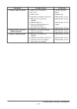
Immediately

after starting

1) Run the engine at idle for 5 min-

utes after starting off.

2) Check each part for leakage of oil,

gas, and air, and take proper mea-

sure.

1) Applying load abruptly If load is

abruptly applied with the engine

and turbocharger rotating

unsmoothly, such parts that a suffi-

cient amount of oil has not reached

can be seized up.

2) Leakage of oil, gas, and air (espe-

cially, oil leak) causes drop in oil

pressure and loss of oil results in

seizure of the bearing.

During operation

Check the followings:

1) Oil pressure At idle: 0.8 kg/cm

2

or

more At full load: 3.0 ~ 4.8 kg/cm

2

2) If unusual sound or vibration is

heard or felt, reduce engine revolu-

tions slowly and locate the cause.

1) Excessively low oil pressure caus-

es unusual wear or seizure of the

bearing. Too high pressure causes

oil leakage.

2) The engine is operated continuously

with unusual sound or vibration not

corrected, it can be damaged

beyond repair.

When stopping

the engine

1) Run the engine at idle for 5 min-

utes before stopping.

1) If the engine is put to a stop after

being operated at high load, heat

from the red-hot turbine blades is

transmitted to the bearing portion

and burns oil to cause seizure of the

bearing metal and rotating shaft.

Summary of Contents for DE12T

Page 1: ... attention Important Reassembly Tighten to specified torque Align the marks Use special tools of manufacturer s Directional Indication Lubricate with oil Inspection Lubricate with grease Measurement During engine maintenance please observe following instructions to prevent environmental damage Take old oil to an old oil disposal point only Ensure without fail that oil will not get into the sea or ...

Page 2: ......

Page 3: ...ication System 2 16 Air Removal of Fuel System 2 6 Fuel System 2 17 Fuel Supply Pump 2 7 Cooling System 2 18 Turbocharger 2 8 Fan Belt 2 19 Starting Motor 2 9 Air Cleaner 2 20 Electrical Equipment 2 10 Intercooler 2 21 Diagnosis and Remedy 2 11 Valve Clearance Adjust Procedure 2 22 Engine Inspection 3 DISASSEMBLY AND REASSEMBLY OF MAJOR COMPONENTS 48 3 1 Disassembly 3 3 Reassembly 3 2 Inspection a...

Page 4: ...NTS 111 6 1 Fuel Injection Pump 6 4 Turbocharger 6 2 Cooling System 6 5 Air Intake System 6 3 Lubricating System 6 6 V belts 7 SPECIAL TOOL LIST 174 Appendix Part After service center Applications for Daewoo Engine Worldwide Network ...

Page 5: ...ration for the first time read the operating instructions carefully and familiarize yourself with the critical points If you are unsure ask your DAEWOO representative For reasons of safety we recommend you attach a notice to the door of the engine room prohibiting the access of unauthorized persons and that you draw the attention of the operating personal to the fact that they are responsible for ...

Page 6: ...he operation The fluid which flow out can cause injury Fuel is inflammable Do not smoke or use naked lights in its vicinity The tank must be filled only when the engine is switched off Keep service products anti freeze only in containers which can not be confused with drinks containers Comply with the manufacturer s instructions when handling batteries Caution Accumulator acid is toxic and caustic...

Page 7: ...erature equalization can take place Never put cold coolant into an overheated engine See Maintenance and care Do not add so much engine oil that the oil level rises above the max marking on the dipstick Do not exceed the maximum permissible tilt of the engine Serious damage to the engine may result if these instructions are not adhered to Always ensure that the testing and monitoring equipment for...

Page 8: ...ear protective gloves Clean skin which has been in contact with engine oil Wash thoroughly with soap and water A nailbrush is an effective aid Certain products make it easier to clean your hands Do not use petrol Diesel fuel gas oil thinners or solvents as washing agents After washing apply a fatty skin cream to the skin Change oil soaked clothing and shoes Do not put oily rags into your pockets E...

Page 9: ...d be prepared for installation as normal function of the parts can not be maintained if these parts are reused 7 To facilitate proper and smooth reassemble operation keep disassembled parts neatly in groups Keeping fixing bolts and nut separate is very important as they vary in hardness and design depending on position of installation 8 Clean the parts before inspection or reassembly Also clean oi...

Page 10: ...lti hole 5 N0 31 Multi hole 5 N0 29 Fuel injection pressure kg cm2 220 220 160 220 Compression pressure kg cm2 28 at 200rpm Intake and exhaust valve clearance at cold mm 0 3 Intake valve Open at 18 B T D C 18 2 B T D C Close at 34 A B D C 32 2 A B D C Exhaust valve Open at 46 B B D C 69 8 B B D C Close at 14 A T D C 29 8 A T D C Lubrication method Full forced pressure feed type Oil pump type Gear ...

Page 11: ...17 294 2 000 115 1 400 1 000 1 025 2 250 2 275 TIER I EBIEE 17 282 2 000 110 1 400 1 000 1 025 2 250 2 275 DE12TIA EBILA 14 305 2 100 115 1 400 975 25 2 310 50 EBILB 14 302 2 100 132 1 200 1 000 25 2 380 2 410 EBILC 14 302 2 100 132 1 200 1 000 25 2 380 2 410 EBILD 17 282 2 100 132 1 200 1 000 25 2 380 2 410 ECIEA 17 282 2 000 132 1 200 1 000 25 2 380 2 410 ECIEB 6 5 7 294 2 000 115 1 400 1 000 1 ...

Page 12: ...NGINE SPECIFICATIONS REVOLUTION rpm POWER OUTPUT ps 1000 200 2000 1500 FUEL CONSUMPTION g ps h 170 130 110 TORQUE kg m 160 100 300 120 150 EE6OM001 Performance ISO 1585 SAE J1349 Output rated 323 ps 2 000 rpm Torque max 135 kg m 1 400 rpm Fuel consumption rated 160 g ps h ...

Page 13: ...ICATIONS REVOLUTION rpm POWER OUTPUT ps 1000 200 2000 1500 FUEL CONSUMPTION g ps h 170 120 100 TORQUE kg m 160 100 300 110 150 EE6OM002 Performance ISO 1585 SAE J1349 Output rated 297 ps 2 000 rpm Torque max 120 kg m 1 400 rpm Fuel consumption rated 158 g ps h ...

Page 14: ...FICATIONS REVOLUTION rpm POWER OUTPUT ps 1000 200 2000 1500 FUEL CONSUMPTION g ps h 170 110 90 TORQUE kg m 160 100 300 100 150 EE6OM003 Performance ISO 1585 SAE J1349 Output rated 260 ps 1 900 rpm Torque max 110 kg m 1 400 rpm Fuel consumption rated 155 g ps h ...

Page 15: ...NS REVOLUTION rpm POWER OUTPUT ps 1000 250 2100 1400 FUEL CONSUMPTION g ps h 170 130 90 TORQUE kg m 150 220 280 1800 160 110 180 150 EE6OM004 Performance ISO 1585 SAE J1349 Output rated 285 ps 2 100 rpm Torque max 130 kg m 1 200 rpm Fuel consumption rated 160 g ps h ...

Page 16: ...ONS 1 Cooling water pump 2 Valve 3 Valve spring 4 Oil filler 5 Tappet 6 Push rod 7 Piston pin 8 Piston 9 Piston chamber 10 Crank shaft pulley 11 Vibration damper 12 Oil pump 13 Crank shaft 14 Oil suction pipe 15 Connecting rod 16 Cam shaft 17 Flywheel EE6OM018 1 2 3 4 5 6 7 8 9 10 11 12 13 14 15 16 17 ...

Page 17: ...GULATIONS ENGINE SPECIFICATIONS EE6OM019 1 2 3 4 5 6 7 8 9 10 11 1 Oil filter 2 Cylinder block 3 Fuel injection pump 4 Oil cooler 5 Fuel filter 6 Fuel injection nozzle 7 Rocker arm 8 Cylinder head cover 9 Exhaust manifold 10 Piston ring 11 Air pipe ...

Page 18: ...0 1 9 0 1 9 0 1 9 0 1 9 0 1 EE6OM005 1 Fly wheel 2 Flywheel housing 3 Lifting hook 4 Oil cooler 5 Intake manifold 6 Air heater 7 Water outlet 8 Oil filler cap 9 Oil filter 10 Oil drain plug 11 Oil pan 12 Fuel injection pump 13 Mounting bracket 14 Alternator 15 Fuel filter 16 Air pipe 17 Cooling water pump 18 Exhaust manifold 19 Crank shaft pulley 20 Vibration damper 21 Mounting bracket 22 Starting...

Page 19: ... 3 Lifting hook 4 Oil cooler 5 Intake manifold 6 Air heater 7 Air pipe Intercooler to intake manifold 8 Water outlet 9 Oil filler cap 10 Oil filter 11 Oil drain plug 12 Oil pan 13 Fuel injection pump 14 Mounting bracket 15 Alternator 16 Fuel filter 17 Cooling water pump 18 Turbocharger 19 Exhaust manifold 20 Crank shaft pulley 21 Vibration damper 22 Mounting bracket 23 Starting motor 24 Air pipe T...

Page 20: ...el and serial number because of their location Engine serial No example 2 DE12T DE12T 5 00001 EA Engine serial No example 3 DE12TI DE12TI 5 00001 EA Engine serial No example 4 DE12TIS DE12TIS 5 00001 EA 16 TECHNICAL INFORMATION EE6OM020 Engine Number Engine Suffix EBHEA Serial No Production Year 2005 Engline Model Engine Suffix EBIEA Serial No Production Year 2005 Engline Model Engine Suffix ECIEA...

Page 21: ...he DE12 series diesel engines dis charge very low level of hazardous exhaust gases such as smoke nitro gen oxide hydrocarbon or carbon monoxide and thus ensure high per formance and low fuel consumption 2 2 2 Cylinder block The cylinder block is a single piece of alloy cast iron To increase its stiffness it is extended to a level below the crankshaft center line The engine has replaceable dry cyli...

Page 22: ... and delivers it through the oil cooler and oil filter to the main distributor gallery and from there to the main bearings big end bearings and camshaft bearings as well as to the small end bearings and the rocker arms The injection pump and the turbocharger are also connected to the engine lubricating system The cylinder walls and timing gears are splash lubricated Each cylinder has an oil jet pr...

Page 23: ...oils are also recommended If long oil change intervals are to be used ACEA E3 oil must be used 19 TECHNICAL INFORMATION Valve 5bar Valve 2bar Valve 10bar EQM4005L A C W P BRG T C I P Rocker arm Cam shaft Piston Con rod bearing Main bearing Main oil gallery Relief valve 4 4bar Oil cooler Oil filter Oil pump Air compressor Water pump Turbocharger Fuel injection pump Oil spray nozzle 1 3bar First oil...

Page 24: ... Change the oil filter cartridge simulta neously at every replacement of engine oil 20 TECHNICAL INFORMATION Engine oil capacity Engine in Oil pan Total model Vehicle Max Min lit lit lit DE12T TI TIA TIS Excavator 25 17 28 Loader 21 17 24 EQM4010I Oil filter Cartridge Oil filter head Oil filter head ass y Cartridge EE6OM025 ...

Page 25: ...uel and leak fuel from the nozzle flow through the return pipe back to the tank A strainer is arranged ahead of the fuel feed pump 1 Fuel filter 7 Fuel injection pipe 1a Fuel water drain plug 8 Fuel pipe feed pump filter 2 Air bleeding screw for fuel filter 9 Fuel tank 3 Injection nozzle 10 Fuel return pipe 4 Overflow tube 11 Suction pipe 5 Fuel pipe filter injection pump 12 Feed pump 6 Overflow v...

Page 26: ... fuel economy Number 2 D fuel whenever possible When temperatures are below 7 C 20 F use Number 1 D fuel If Number 1 D fuel is not available the mixture of one kerosene to two gallons of Number 2 D fuel can be used Once kerosene has been added the engine should be run for several minutes to mix the fuel 2 6 4 How to select fuel oil Fuel quality is an important factor in obtaining satisfactory engi...

Page 27: ...5 52 131 55 Min F C Viscosity Kinematic D 445 1 3 2 4 1 9 4 1 1 8 10 CST 100 F 40 C Cloud Point F D 2500 See Note 1 See Note 1 See Note 1 Sulfur Content D 129 0 5 0 5 0 15 wt Max Carbon Residue D 524 0 15 0 35 0 1 on 10 wt Max Accelerated Stability Total Insolubles D 2274 1 5 1 5 mg 100 ml Max Ash wt Max D 482 0 01 0 01 Cetane Number Min D 613 45 45 45 Distillation D 86 Temperature F C IMP Typican...

Page 28: ...t of loss of coolant shut the engine down Check the coolant level of the expansion tank by removing the expansion tank filler cap and add coolant if necessary When injecting antifreeze solution first drain out the old coolant from the cylinder block and radiator and then clean them with cleaning solution Be sure to mix soft water with antifreeze solution 24 TECHNICAL INFORMATION Reserve tank Radia...

Page 29: ...The density of above solution and additive must be inspected every 500 hours to maintain it properly NOTE The proper density control of antifreezing solution and rust preventing additive will be able to prevent the rusting effectively and maintain the stable quality of engine For the improper control might give the fatal damage to the cooling water pump and cylinder liners detail care is needed Si...

Page 30: ...green or so with the green color indication of test paper storage bottle confirm the density Then the density indication must be in the hue range of 33 to 50 6 The brown at the middle of test paper and the lower pink color indication represent the additive state for rust prevention and the proper range is that the meeting numerical value of brown vertical and pink color horizontal locates in the r...

Page 31: ...lops leases or the coolant is heavily contaminated dull brown mechanically contaminated grey or black sings of a leakage on the water pump casing clean the cooling system prior to removing that water pump as follows a Drain coolant b Remove thermostats so that the whole cooling system is immediately flown through when cleaned c Fill the cooling system with a mixture of potable water and 1 5 by vol...

Page 32: ...ection force F is applied mid way between the belt s tangent points with the pulley T 0 015 x S about 1 5 mm per 100 mm T 0 015 x S mm T Deflection S Span S C2 mm 2 9 Air Cleaner In case that elements are deformed damaged or if the air cleaner has a crack replace it By the definite interval the elements must be cleaned and replaced 28 TECHNICAL INFORMATION S SPAN d T F C D EB5O6001 Water pump pull...

Page 33: ...the engine output is decreased and engine malfunction is occurred So you always check whether the intake air systems like air filter element are worn or polluted 29 TECHNICAL INFORMATION 냉각 공기 냉각 휀 과급기로부터 온 뜨거운 공기 공기 냉각기를 통과한 공기 공기온도 최대 50 C 공기 냉각기와 라디에이터 라디에이터와 공기 냉각기 일체형 Air air intercooler with radiator combined radiator Air flow by cooling fan Sucker type fan Hot air by turbo charger compresso...

Page 34: ...the exhaust valves of 6 then 1 cylinder become the compression state of top dead center 2 Therefore adjust the valve clearance corresponding to of lower figure At this time there are no force on the push rods of 1 cylinder 3 Rotating the crankshaft by one revolution 6 cylinder become the compression state of top dead center 4 Thereafter adjust the valve clearances corresponding to of lower figure ...

Page 35: ...ture 20 C Engine rotation 200rpm 2 13 Injection Nozzle Install a nozzle on the nozzle tester If the inspected injection pressure is less than the specified value adjust using the adjust ing shims Check the atomizing state and replace it if abnormal EFM1004I EFM1005I Standard value 28kg cm2 over Limit value 24kg cm2 Difference Within L 10 between each cylinder EFM1006I Normal Abnormal Abnormal Engi...

Page 36: ...el System The suction room of fuel injection pump has the function of air removal continuously during the operation through a relief valve In case that the suction room lacks fuel at all for instance in case of new installation of injec tion pump after loosening the air removing screws of cartridge filter respectively remove the air by operating the manual pump of fuel supply pump until bubble wil...

Page 37: ...ed air frequent cleaning must be done on the impellers Tear down the impeller casing attention be careful not to bend and must clean with non acid solvent solution If necessary use plastic scraper If impeller is severely polluted dip the impeller into solution and may be better to clean it with stiff brush Then one thing to beware is to dip only impeller part and so do not support by impeller but ...

Page 38: ...n the key switch is placed in the START position air heater is continuously heated to facilitate starting operation and to reduce white smoke during 19 seconds automatically If the coolant temperature is above 15 C air heater needs not be heated Operation 3 After the engine is cranked convert the key switch to the ON position Behavior As the engine is cranked air heater is heated for 150 seconds a...

Page 39: ...oltage The alternator should not be operated except with the regulator and battery connected in circuit to avoid damage to the rectifier and regulator The alternator is maintenance free nevertheless it must be protected against dust and above all against moisture and water Operate the alternator according to the instructions given in the chapter EE6OM027 24V X 50A EE6OM028 Wiring Diagram SG P B R ...

Page 40: ...hen a coat of grease should be applied again Always protect starter motor against moisture Warning Always disconnect the battery earth cable before starting work on the electrical system Connect up the earth cable last as there is otherwise a risk of short circuits 36 TECHNICAL INFORMATION EE6OM021 Switch terminal Battery terminal Earth terminal M10 x 1 5 24V X 6 6KW EE6OM022 Wiring Diagram Swtich...

Page 41: ... compression pressure Normal Too low Inspect of other parts Check valve clearance Normal Adjust Check cylinder head gasket Replace Normal Engine disassembly valve assembly piston cylinder liner etc Fuel Inspect amount of fuel None Replenish Inspect fuel injection No injection Continuous operation after air removal Inspect injection timing Inspect injection nozzle injection pressure injection state...

Page 42: ...diator Repair Replace Repair Replace Repair Replace Repair Replace Replenish Replace Replace Damage Check cooling water pump Engine disassembly Fuel unit Inspect fuel quality Poor Clean and replace with specified fuel Inspect cooling water leakage External Internal Retighten Replace Engine disassembly Operating state 1 Overload 2 Radiator core clogged 3 Continuous over run Fuel excessive supply Ch...

Page 43: ... Replace Inspect injection nozzle injection pressure atomizing state Adjust Replace Check injection timing Adjustment Disassemble engine or injection pump Inspect injection pipe Others Inspect air cleaner Clean Relpace Inspect engine control rod link cable etc Adjust Adjust Inspect cylinder head gasket for damage Engine disassembly valve assembly Check valve clearance Installation improper Check f...

Page 44: ...ount Normal Normal Normal Normal Check cooling temperature Inspect oil quality Check oil relief valve Disassemble engine Too high Refer to engine overheat Water fuel mixed in oil Disassemble engine or injection pump Improper Replace with recommended oil Too low Use recommended oil replenish Retighten Replace ...

Page 45: ...sassemble injection pump Inspect head gasket Disassemble engine valve assembly piston cylinder liner etc Adjust Replace Adjust Adjust Check valve clearance Replace Causes according to Use Conditions 1 Overload 2 Frequent use of low gear position at high speed 3 Frequent use of high gear position at low speed 4 Clutch slip 5 Too low tire inflation pressure Oil leakage Retighten Replace Repair Repla...

Page 46: ...Check compressed pressure Engine disassembly piston cylinder liner Disassemble cylinder head valve stem seal Inspect air cleaner Clean Replace 7 Engine Knocking Inspect combustion of fuel oil carbon residue of exhaust gas Unconfirmed Inspect compressed pressure Inspect injection pump Adjust Check fuel quality Use specified fuel Too low Check valve clearance and cylinderhead gasket for damage Repla...

Page 47: ...connections Repair Replace Generator Check fan belt tension damage Normal Normal Electrolytic liquid s standard Replenish Battery room damage Replace Battery self discharge Charging Battery over charging Inspect generator Voltage regulator Check charged stated Discharging Disassemble generator Voltage regulator Abnormal Adjust Replace ...

Page 48: ...essure Adjust or replace improper or stuck Supply pump s function lowered Repair or replace Fuel pipe system clogged Repair Air suction amount insufficient Clean or replace air cleaner Turbocharger poor Repair or replace 2 Output insufficient when Compression pressure insufficient Disassemble engine in acceleration Injection timing incorrect Adjust Fuel injection amount insufficient Adjust injecti...

Page 49: ...place grind crankshaft Oil supply insufficiency as clogging Clean oil passage at oil passage progresses 3 Piston piston pin Piston clearance increase as the Replace piston piston ring piston ring wear of piston and piston ring progresses Wear of piston or piston pin Replace Piston stuck Replace piston Piston insertion poor Replace piston Piston ring damaged Replace piston 4 Others Wear of cranksha...

Page 50: ...ing Piston ring opening s disposition improper Correct position Piston skirt part damaged or Replace piston abnormal wear Oil ring s oil return hole clogged Replace piston ring 2 Oil level lowered Looseness of valve stem guide Replace in set Wear of valve stem seal Replace seal Cylinder head gasket s leak Replace gasket 3 Oil leak Looseness of connection parts Replace gasket repair Various parts p...

Page 51: ...ry Every Every Every Remark 50hrs 200hrs 500hrs 600hrs 1200hrs Check for leakage hoses clamp Check the water level Cooling Change the coolant water System Adjust the V belt tension Every 2 000hrs Clean the radiator Check for leakage Lubrication Check the oil level gauge System Change the lubricating oil 1st Replace the oil filter cartridge 1st Intake Check the leakage for Exhaust intercooler hoses...

Page 52: ... any damage to them 3 1 2 Cooling water Remove the radiator cap Open the drain plug at the radiator lower part to drain the coolant as the right figure CAUTION When removing radiator filler cap while the engine is still hot cover the cap with a rag then turn it slowly to release the internal steam pressure This will prevent a person from scalding with hot steam spouted out from the filler port Rem...

Page 53: ...draining out the engine oil 3 1 4 Cooling fan Remove the flange fixing bolts then take off the flange and cooling fan 3 1 5 V Belt Loosen the tension adjusting nuts on the alternator and take off the alterna tor belts 3 1 6 Oil level gauge guide tube Loosen the flange nut installed on the ladder frame to remove the guide tube 49 DISASSEMBLY EQM3001I EQM3004I EE6OM008 Alternator EQM3005I ...

Page 54: ...ve the rubber hose 3 1 9 Intercooler Tear down the various hoses and air pipes from the inter cooler Remove the intercooler fixing bolts and tear it down 3 1 10 Fuel injection pipe Unscrew the hollow screws to disas semble the fuel return pipe Remove the nuts installed on the fuel injection pump and nozzles then dis assemble the injection pipe 50 DISASSEMBLY EE6OM029 EA6M2001 EQM3009I ...

Page 55: ...e intake manifold fixing bolts then disassemble the intake manifold 3 1 13 Turbo charger Release the clamp screw of the rub ber hose connected to the intake manifold and take off the intake pipes both simultaneously Unscrew the exhaust pipe bracket fix ing bolts release the nuts installed on the turbocharger then disassemble the exhaust pipe Remove the turbocharger after remov ing the oil supply p...

Page 56: ...ump unscrew the ther mostat fixing bolts then disassemble the thermostat housing Disassemble the thermostat housing and remove the thermostat Disassemble the water pipe by unscrewing the bolts and nuts installed on the cylinder head 3 1 16 Starter Unscrew the starter fixing bolts then disassemble the starter 3 1 17 Cooling water pump Remove the water pipe connected to the expansion tank Remove the...

Page 57: ... the bracket from the cylinder block NOTE Do not interchange the shims as they must be installed in their original positions at reassembly 3 1 19 Oil filter Using a filter remover wrench remove the oil filter cartridge Remove the pipe connected to the oil cooler Loosen the oil filter fixing bolts and disassemble the oil filter head from the cylinder block 3 1 20 Vibration damper Unscrew the pulley...

Page 58: ...t damage to them 3 1 23 Fuel injection pump drive Remove the dowel pin for the steering pump Unscrew the injection pump drive shaft bearing housing fixing bolts and remove the injection pump drive assembly in which the shaft gear bearings and housing are put togeth er 3 1 24 Cylinder head cover Unscrew the cover fixing bolts and disassemble the cover Keep the bolts in an assembly state so that the...

Page 59: ...oving jig NOTE Do not disassemble the nozzle tube if coolant or gas etc does not come out during engine operation 3 1 27 Cylinder head Unscrew the cylinder head fixing borts and take off the cylinder head Remove the cylinder head gasket 3 1 28 Valve and stem seal Compress the valve spring retainer using a jig and take off the valve cot ter pins Disassemble the valve springs and retainers Take off ...

Page 60: ...il pan Stand the engine with the flywheel housing facing the bottom Release the oil pan fixing bolts remove the stiffeners then disassem ble the oil pan 3 1 31 Oil pump and pipe Unscrew the oil suction pipe bracket bolts releasing the pipe fixing bolts then disassemble the oil suction pipe assembly Disassemble the oil pipe feeding oil from the oil pump to the cylinder block Unscrew the oil pump fi...

Page 61: ... direction of piston Remove the piston pin snap rings take off the piston pin then discon nect the connecting rod from the pis ton Disassemble the piston rings using ring pliers Use care not to interchange the dis assembled parts and keep them in the sequence of cylinder No 3 1 34 Cylinder liner Disassemble the cylinder liner using a liner puller 57 DISASSEMBLY EAMD037I EAMD040I Piston ring jig ...

Page 62: ...il seal Take off the rear oil seal using an oil seal disassembling jig If only the inside guide ring is removed use a special tool to take off the outside seal 3 1 37 Flywheel housing Loosen the housing fixing bolts and disassemble the flywheel housing 3 1 38 Cam shaft and tappet Remove the cam shaft gear Take off the cam shaft gear and thrust washer Take out the cam shaft care not to damage the c...

Page 63: ...41 Crank shaft Remove the main bearing cap fixing bolts in the opposite direction of assembling Maintain the removed bearing caps in the order of cylinders Temporarily install the bolts at the both side of crankshaft and lift the shaft with a rope NOTE Do not mingle with the metal bear ings and bearing caps randomly To prevent mixing temporarily assem ble the metal bearings to the corre sponding b...

Page 64: ...3 1 42 Oil spray nozzle Unscrew the fixing bolt and remove the oil spray nozzles 60 DISASSEMBLY ...

Page 65: ...efully remove carbon from the lower lace of the cylinder head using nonmetallic materi al to prevent scratching of the valve seat faces Check the entire cylinder head for very fine cracks or damage invisible to ordinary sight using a hydraulic tester or a magnetic flaw detector 2 Distortion at the lower face Measure the amount of distortion using a straight edge and a feeler gauge at six positions...

Page 66: ...ar is beyond the limit replace the valve Valve seat contacting faces Check the valve seat contacting faces for scratches or wear and correct the faces with grinding paper as necessary Replace if severely damaged Valve head thickness Measure the valve head thickness and replace the valve if the measured value is beyond the limit 62 INSPECTION AND MEASUREMENT Standard Limit 0 05 mm 0 2 mm EFM2036I 밸...

Page 67: ...acting face between the intake valve seat and exhaust valve seat for valve seat wear and replace if the measured value exceeds the specified limit Install the valve into the valve seat on the cylinder head and check the amount of depression of the valve from the lower portion of the cylinder head using a dial gauge Valve depression If the amount of depression is beyond the specified limit replace ...

Page 68: ...t ed in position then wipe out the lapping compound 4 Valve spring Visual check Visually check the exterior of the valve springs for damage and replace if necessary Functional check Measure free length and spring ten sion with a valve spring tester Refer to appendix Measure the spring inclination with a square Compare the measured value with the standard value to determine whether to replace or re...

Page 69: ... limit 2 Rocker arm Visual check Visually check the face of the rocker arm in contact with the valve stem end for scores and step wear If the wear is small correct it with an oil stone or grinding paper of fine grain size Rocker arm with a considerable amount of step wear should be replaced Diameter of the rocker arm bushing Measure the inside diameter of the rocker arm bushing with an inside micr...

Page 70: ...ect with an oil stone or grinding paper Outside diameter With an outside micrometer measure the tappet outside diameter If the measured value is beyond the limit replace tappets Push rod run out Use a feeler gauge to measure the push rod run out Roll the push rod along a smooth flat surface as shown in the figure 66 INSPECTION AND MEASUREMENT 1 요철 2 균열 3 정상 4 비정상 EA0M4070 EDM2061I EA0M4073 간극 게이지 ...

Page 71: ...mshaft bush With an outside micrometer mea sure the camshaft journal diameter Measure the inside diameter of the camshaft bushing on the cylinder block using a cylinder bore indicator and compare the measured value with the camshaft outside diameter to determine the clearance Clearance Replace the bushing if the measured value is beyond the specified limit 67 INSPECTION AND MEASUREMENT C A A B B D...

Page 72: ...eplace the thrust plate 3 2 6 Cam shaft 1 Defect check Visually check the crankshaft journal and crank pins for scores or cracks Using a magnetic particle test and color check inspect the crankshaft for cracks and replace the crankshaft which has cracks 2 Wear With an outside micrometer measure the diameter of the crankshaft jour nals and pins in the directions as shown and compare the measured va...

Page 73: ... standard size Undersize bearings are available in 4 different sizes as indicated above and the crankshaft can be reground to the above sizes NOTE When regrinding the crankshaft as described below the fillet section R should be finished correctly Avoid sharp corners or insufficient fillet Standard values of R Crankshaft Pin R 5 0 2 Crankshaft journal R 5 0 2 3 Crankshaft run out Support the cranks...

Page 74: ...e diameters of crankshaft journals to determine the oil clearance Main bearing oil clearance Connecting rod bearing clearance Install the connecting rod bearing in the connecting rod bearing cap tight en the connecting rod cap bolts to the specified torque then measure the inside diameter Compare the two values obtained through measurement of connecting rod bearing inside diameter with the outside...

Page 75: ...he bolts to specified torque unscrew out one bolt completely then measure the clearance between the bearing cap and cylinder block using a feeler gauge Connecting rod bearing crush Install the bearing and cap in the con necting rod big end retighten the bolts to specified torque unscrew out one bolt completely then measure the clearance between the bearing cap and connecting rod big end using a fe...

Page 76: ...ylinder liner inside diameter at 3 points cylinder top ring contacting face middle and oil ring contacting face on BDC in a direction at an angle of 45 Take the mean value with the largest and smallest values excepted The clearance is computed by subtracting the piston outside diameter from the cylinder liner inside diameter Replace either piston or cylinder liner whichever damaged more if the cle...

Page 77: ...g in the piston ring groove With a feeler gauge measure side clearance of each ring and replace either the ring or piston if the mea sured value is beyond the specified limit 4 Piston ring tension With a tension tester measure piston ring tension Replace the piston ring if the measured value is beyond the limit 73 INSPECTION AND MEASUREMENT EA0M4032 간극 게이지 Standard Limit Top ring 0 30 0 45 mm 1 5 ...

Page 78: ... replacing the piston be sure to replace the piston pin together 3 2 11 Connecting rod 1 Distorsion Check the connecting rod for distortion As shown in the figure below install the connecting rod to the connecting rod tester and check for distortion using a feeler gauge If the connecting rod is found distorted never re use it but replace with a new one 2 Holes alignment parallelism Measure the ali...

Page 79: ... connecting rod 3 2 12 Fuel injection nozzle Insert a seal ring and injection nozzle on the cylinder head Measure the clearance between the cylinder head bottom and nozzle tip If the measured values are beyond the limit replace the seal ring 75 INSPECTION AND MEASUREMENT A B 연료분사 노즐 실린더 헤드 노즐 튜브 Fuel injection nozzle Cylinder head Nozzle tube EQM8010I Limit 0 5 mm Standard DE12T TI TIA DE12TIS A 1...

Page 80: ...r being reassembled Check the bolts for looseness after preliminary reassembly After completing the engine reassembly operation check if there is missing parts or short age of parts Keep your hands clean during the working 3 3 2 Cylinder block Cover the floor of the workshop with wood plate or thick paper to prevent damage to the cylinder head and place the cylinder block with the head fitting sur...

Page 81: ... rotates smoothly 3 3 5 Crankshaft Install the main bearing machined with two holes in the cylinder block so that the key is aligned with the key groove then apply oil to the bearing surface Heat the crankshaft gear for at least 10 minutes to 120 C then apply sealant Loctite 641 to the inside wall of the heated crankshaft gear evenly before inserting it to the end of crankshaft 77 REASSEMBLY EDM20...

Page 82: ... block by tightening the fixing bolts Install the oiled thrust washers with the oil groove facing outward Install the bearing and thrust washers to the bearing cap and apply oil to the bearing and thrust washers Install the bearing cap by matching the cylinder block No with the bearing cap No 78 REASSEMBLY EAMD077I 3 4 5 6 7 2 1 EAMD078I ...

Page 83: ...3 5 2 6 1 7 Check to see that the assembled crankshaft turns smoothly 3 3 6 Flywheel housing Temporarily install the guide bar on the cylinder block Apply gasket to the cylinder block Using the dowel pin and guide bar install the flywheel housing and tight en the fixing bolts in a diagonal sequence to specified torque 3 3 7 Rear oil seal Apply lubricating oil to the outside of the oil seal and fly...

Page 84: ...olts using a torque wrench in a diagonal sequence to specified torque 3 3 9 Magnetic pick up sensor Move the lock nut to hexagonal side of sensor completely Rotate Clcokwise the pick up sensor on flywheel housing until the end of it reach on fly wheel ring gear Then rotate Counter clockwise the pick up sensor for 270 gap 1 0 mm and fix lock nut Tolerance limit is 27 gap L 0 1 mm 80 REASSEMBLY EAMD...

Page 85: ...ck install the idle gear pin Install the idle gear by coinciding the marks impressed on the crank gear cam gear fuel injection pump drive gear and idle gear Install a thrust washer on the idle gear and tighten to specified torque Check and adjust the amount of back lash between gears using a feeler gauge 81 REASSEMBLY EAMD083I 아이들 기어 핀 EA8M3004 아이들 기어 핀 Idle gear pin Idle gear pin Torque 3 8 kg m ...

Page 86: ...ning with the oil pan fitting face 3 3 14 Front oil seal Apply lubricating oil to the outside of the oil seal and timing gear case inside diameter and fit them over the crankshaft then assemble the oil seal using an oil seal fitting jig 3 3 15 Cylinder liner Stand the cylinder block so that the flywheel faces downward Thoroughly clean the liner flange fit ting surface and bore inside with com pres...

Page 87: ... side machined with key groove on the bearing of the con necting rod big end and the mark of impressed on the inside of the piston face each other in opposite directions On the piston head sur face the longer side of connecting rod big end is in opposite direction from the valve seating surface as well as in the same direction with the narrow margin of combustion chamber Install the snap rings and...

Page 88: ...and insert the piston into the cylinder so that the ring may not be damaged by the fillet of the liner Install the bearing in the connecting rod cap and apply oil Make sure that the manufacture serial numbers impressed on the connecting rod cap and connecting rod big end are identical and install the connecting rod cap by aligning it with dowel pin Wet the fixing bolts with oil semi tight en them ...

Page 89: ...assemble the oil pump with specified torque Assemble the oil suction pipe with the delivery pipe then install the bracket on the bearing cap 3 3 19 Oil pan Mount gasket and put the oil pan thereon Place stiffeners and tighten bolts Align the bolt holes with gasket holes to prevent damage to the gasket and tighten to specified torque 85 REASSEMBLY EAMD094I EAMD036I EAMD095I Torque 4 4 kg m EQM3076I...

Page 90: ...hen install cotter pin Tap the valve stem lightly with a rub ber hammer to check that the valve is assembled correctly 3 3 21 Nozzle tube Apply sealant LOCTITE 620 to the nozzle tube and place the O ring over the cylinder head fitting face on the nozzle tube then install the nozzle tube in the cylinder head Install a guider of the nozzle tube insert assembly Guider Expander on the cylinder head th...

Page 91: ...22 Rocker arm assembly Apply lubricating oil to the rocker arm bush and shaft and assemble the intermediate bracket with the rocker arm using fixing bolts Semi install valve clearance adjusting bolts onto the rocker arm Install the spring rocker arm bracket rocker arm spring washer and snap ring in the described sequence Install the rocker arm and bracket in the same direction Test pressure 2 kg c...

Page 92: ...d on the cylinder block by aligning the holes with dowels Check the inside of combustion cham ber for foreign substances and care fully mount the cylinder head assem bly in the block by aligning the dowel pin with the dowel pin hole Be careful not to damage the head gasket If the dowel pin is not in align ment lift the cylinder head again and then remount it 88 REASSEMBLY TOP EAMD101I Cylinder hea...

Page 93: ...just the valve clearance as follow ing guide 89 REASSEMBLY EAMD102I 12 3 2 1 4 8 9 5 6 7 10 11 13 14 EAMD103I Type 1 Type 2 Type 3 12 9T Type 4 12 9T Type 5 10 9T M14x1 5x153 M14x1 5x150 M14x1 5x153 M14x1 5x150 M14x1 5x150 Tighten 1st 6 kg m 1st 6 kg m 1st 7 kg m 1st 6 kg m torque 24 5 kg m 2nd 180 2nd 90 90 2nd 90 90 2nd 90 90 Finished 150 Finished 30 Finished 90 TY 12 9T TY 10 9T TY DL08 ...

Page 94: ...ylinder s valves overlap In time adjust the valve clearance corresponding to of lower figure Rotating the crankshaft by one revolution 6 cylinder become the compression state of top dead center Adjust the valve clearance corresponding to of lower figure After reinsuring the valve clearances retighten if necessary No 1 Cylinder is located at the side where flywheel was installed Adjust valve cleara...

Page 95: ...and thermostat Install the water pipe onto the cylin der head Insert the thermostat in the housing With socket head bolt install the thermostat housing onto the water pipe 3 3 26 Oil cooler Install the oil cooler onto the oil cool er cover Carefully apply the gasket to prevent oil leakage Do not damage the gasket and install the cover onto the cylinder block Connect a connection pipe between the w...

Page 96: ...the cartridge using a filter wrench 3 3 28 Injection pump Install the injection pump bracket in the cylinder block After measuring the amount of run out with an alignment setting jig disas semble the bracket adjust the shims then reassemble it Mount the top bottom adjusting shims in the bracket and then mount the fuel injection pump Tighten the fixing bolts in a diagonal sequence to specified torq...

Page 97: ...housing Turn the timer until the notch mark of the indicator plate attached to the fuel injection pump is aligned with the notch mark of the timer Tighten the Coupling fixing bolts and nuts to specified torque Tighten the drive shaft connecting flange fixing bolts to specified torque Install the oil delivery pipe and return pipe 93 REASSEMBLY Timing check hole Injection timing notch mark Flywheel ...

Page 98: ...nect a water pipe to the expan sion tank 3 3 31 Exhaust manifold Install the exhaust manifold gasket over the stud bolts by aligning the gasket with the exhaust port on the cylinder head so that the face and back of the gasket can be positioned correctly Semi assemble the exhaust mani fold and install the heat resisting plate 3 3 32 Turbocharger Fit a new gasket over the stud bolts of the exhaust ...

Page 99: ...etely 3 3 34 Starter Assemble the starter in position on the flywheel housing 3 3 35 Intake manifold Fit a gasket on the intake manifold before assembling the intake mani fold Mount the air heater gasket on the intake manifold then assemble the air heater with the intake manifold Connect the air hoses to the boost compensator mounted on the fuel injection pump EE6OM031 EAMD121I EQM3100I ...

Page 100: ... the air pipe bracket Assemble the fuel feed hose accord ing to the direction of an arrow impressed on the fuel filter head so that fuel can be fed in the sequence of FUEL FEED PUMP FUEL FILTER FUEL INJECTION PUMP 3 3 38 Cylinder head cover Assemble the cover packing with the cover install the cover on the head then tighten the fixing bolts in sequence to specified torque Assemble the breather hos...

Page 101: ...all the cooling fan and flange then tighten the fixing bolts 3 3 41 V belt Install the V belt on the crank pulley and alternator pulley Adjust the V belt tension using the tension adjusting bolt 3 3 42 Cooling fan guide Install the three fan guide brackets then assemble the fan guide and bracket 97 REASSEMBLY EQM3106I EE6OM008 Alternator EQM3108S ...

Page 102: ...3 3 43 Oil level gauge Assemble the oil level gauge and guide tube on the oil pan 98 REASSEMBLY EQM3005I ...

Page 103: ...liding surfaces of a new engine are not lapped enough the oil film can be destroyed easily by overload or overspeed and the engine life time may be shortened Therefore the following things must be obeyed by all means Up to the first 50 hours Engine should be run at fast idling until the temperature of the engine becomes normal operating condition Overload or continuous high speed operation should ...

Page 104: ...ing a cold engine always allow the engine to warm up gradually Never run the engine at full throttle until the engine is thoroughly warmed up Be sure to check the oil level frequently during the first 1 000km 50 hours of operation since the oil consumption will be high until the piston rings are properly seated 4 2 4 Engine oil Check oil level with the oil level gauge and replenish if necessary Ch...

Page 105: ...auge panel 4 3 1 Pressure of lubricating oil The normal pressure comes up to 1 kg cm2 1 0 bar at idling and 3 5 kg cm2 3 0 4 9 bar at maximum speed If the pressure fluctuates at idling or does not reach up to the expected level at high speed shut down the engine immediately and check the oil level and the oil line leakage 4 3 2 Temperature of cooling water The cooling water temperature should be 7...

Page 106: ...hould be used to prevent this unstability Refer to Lubricating System section 4 5 Tuning the Engine The purpose of an engine tune up is to restore power and performance that s been lost through wear corrosion or deterioration of one or more parts or components In the normal operation of an engine these changes can take place gradually at a number of points so that it s seldom advisable to attempt ...

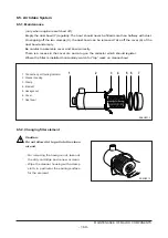
Page 107: ...amber deposits and engine wear At the end of the break in period 1 000km 50hours change the oil sump oil and replace the oil filter cartridge 5 2 2 Oil level gauge Check the oil level in the engine sump daily with a oil level gauge The notches in oil level gauge must indicate the oil level between the max and the min permissible The oil level should be checked with the engine horizontal and only a...

Page 108: ... on the head cover and the lubricating oil in accordance with the oil capacity of the engine through oil filler Be careful about the mixing of dust or contaminator during the supplement of oil Then confirm that oil level gauge indicates the vicinity of its maximum level For a few minutes operate the engine at idling in order to circulate oil through lubrication system Thereafter shut down the engi...

Page 109: ... clockwise with a filter wrench With a rag wipe clean the fitting face of the filter body and the oil filter body so that new oil filter cartridge can be seated properly Lightly oil the O ring and turn the oil filter until sealing face is fitted against the O ring Turn 1 1 4 turns further with the filter wrench Note It is strongly advisable to use DAE WOO genuine oil filter cartridge for replaceme...

Page 110: ...ce of the cold engine are as follows Intake valves 0 3 mm Exhaust valves 0 3 mm 5 3 2 Method of adjusting the valve clearance 1 Loosen the lock nuts using a ring spanner 2 Insert a thickness gauge of 0 3mm between valve stem and rocker arm 3 Turn the adjusting bolts using a screw driver until the gauge can be pulled out with some restriction 4 After the adjustment fix the adjusting bolt not to rot...

Page 111: ...h the recommended fuel Keeping tanks full reduces water condensation and helps keep fuel cool which is important to engine performance Make sure fuel supply valves if used are open To insure prompt starting and even running the fuel system must be primed with the fuel feed pump manually before starting the engine the first time or after a fuel filter change Refill at the end of each day s operatio...

Page 112: ...ith the zinc coating to form powdery flakes which can quickly clog the fuel filters and damage the fuel pump and injection nozzles 5 5 2 Priming pump strainer cleaning Clean the priming pump strainer every 10 000km 200 hours operation The strainer is incorporated in the priming pump inlet side joint bolt Clean the strainer with the compressed air and rinse it in the fuel oil 5 5 3 Bleeding the fue...

Page 113: ...jectors are designed to spray the fuel delivered by the injection pump directly into the spherical combustion chamber in the piston crown The injector consists of the nozzle and the nozzle holder A copper seal fitted to the injector ensures gas tight seating and good heat dissipation The opening pressure of the nozzle is adjusted by means of shims at the com pression spring Install a nozzle to a n...

Page 114: ...ss Do not bend pipes to permanent deformation not for replacing the nozzles either Do not mount any heavily bent pipes Avoid bending the pipes at the ends by more than 2 to 3 degrees In case of faults in the injection system which might have resulted in excessive operating pressures not only the failed part but also the injection line has to be replaced 110 MAINTENANCE AND CARE ...

Page 115: ...tube 11 Suction pipe 5 Fuel pipe filter injection pump 12 Feed pump 6 Overflow valve 13 Injection pump 6 1 2 Injection pump The components relating to the injection pump should be serviced at regular intervals as the plunger and delivery valve may be worn after a given length of time for use and cause the dete rioration of the engine Make sure that servicing should be performed at the professional...

Page 116: ... 65 11101 7368A EBIEC 65 11101 7358A ECIEA 65 11101 7361A ECIEB 65 11101 7362A ECIEC DE12TIS 65 11101 7419 ECIED 65 11101 7396 ECILA 65 11101 7395 ECILB 65 11101 7403 ECILC Engine model Part no Suffix DE12T EBHEA EBHLA DE12TI 65 10101 7300 EBIEA EBIEB DE12TIA 65 10102 6046 EBIEC EBIED EBIEE EBILA EBILB EBILC EBILD DE12TIS 65 10101 7298 ECIEA ECIEB ECIEC ECIED 65 10102 6053 ECILA ECILB ECILC Engine...

Page 117: ...standard 65 10102 6046 Nozzle 5 B N0 31 parts Nozzle holder ass y 65 10101 7300 Opening pressure 220 kg cm2 Fuel Injection pipe IDBOD L 65 10301 6289 N2 2 B N6 650 mm Rack diagram and setting valve at each point Check Rack Pump Injection Q ty on RIG point position speed mm3 1 000st Pressure Test condition for inj pump mmHg mm rpm A 9 0 950 113 3 L 2 Basis B 9 0 700 110 6 L 3 C 6 3 300 13 5 L 1 5 6...

Page 118: ...0 31 parts Nozzle holder ass y 65 10101 7300 Opening pressure 220 kg cm2 Fuel Injection pipe IDBOD L 65 10301 6289 N2 2 B N6 650 mm Rack diagram and setting valve at each point Check Rack Pump Injection Q ty on RIG point position speed mm3 1 000st Pressure Test condition for inj pump mmHg mm rpm A R1 11 3 1 050 155 L 2 650 or more B 6 3 490 16 L 1 5 C R1 700 162 650 or more D R1 2 2 550 120 Govern...

Page 119: ...position mm Rack position mm 14 more R1 11 3 R1 11 3 R1 2 2 Pump speed rpm Boost pressure mmHg Main spring set Notch 13 N 550 rpm C A D B 0 0 500 300 450 1170 12 5 _ 0 1 9 5 _ 0 1 8 4 _ 0 1 8 3 _ 0 1 Idle sub spring set _ 0 1 BCS Stroke 2 2 mm _ 0 1 1110 _ 10 70 1150 EE6OM033 ...

Page 120: ...er ass y 65 10101 7300 Opening pressure 220 kg cm2 Fuel Injection pipe IDBOD L 65 10301 6289 N2 2 B N6 650 mm Rack diagram and setting valve at each point Check Rack Pump Injection Q ty on RIG point position speed mm3 1 000st Pressure Test condition for inj pump mmHg mm rpm A 11 2 1 050 148 L 2 B 6 3 500 20 L 1 5 C R1 12 2 500 180 D R1 0 9 550 161 Governor weight 740 g Lever ratio min max 1 1 2 1 ...

Page 121: ...parts Nozzle holder ass y 65 10101 7300 Opening pressure 220 kg cm2 Fuel Injection pipe IDBOD L 65 10301 6289 N2 2 B N6 650 mm Rack diagram and setting valve at each point Check Rack Pump Injection Q ty on RIG point position speed mm3 1 000st Pressure Test condition for inj pump mmHg mm rpm A 9 4 1 050 114 L 2 B 6 2 500 20 L 1 5 C R1 10 6 500 148 Governor weight 740 g Lever ratio min max 1 1 2 1 1...

Page 122: ...300 Opening pressure 220 kg cm2 Fuel Injection pipe IDBOD L 65 10301 6289 N2 2 B N6 650 mm Rack diagram and setting valve at each point Check Rack Pump Injection Q ty on RIG point position speed mm3 1 000st Pressure Test condition for inj pump mmHg mm rpm A 10 7 1 050 142 L 2 500 or more B 6 4 500 20 L 1 5 C R1 12 3 500 187 500 or more D R1 0 9 500 163 Governor weight 740 g Lever ratio min max 1 1...

Page 123: ... position mm Rack position mm 14 more 6 3 R1 12 3 R1 12 3 R1 1 0 Pump speed rpm Boost pressure mmHg N 550 rpm A C D B 0 300 500 900 1130 1200 0 460 12 7 _ 0 1 10 3 _ 0 1 8 5 _ 0 1 5 5 _ 0 1 Idle sub spring set _ 0 1 Boo com stroke 1 0 mm _ 15 220 EE6OM036 1150 NOTCH 11 NOTCH ...

Page 124: ...0102 6046 Nozzle 5 B N0 31 parts Nozzle holder ass y 65 10101 7300 Opening pressure 220 kg cm2 Fuel Injection pipe IDBOD L 65 10301 6289 N2 2 B N6 650 mm Rack diagram and setting valve at each point Check Rack Pump Injection Q ty on RIG point position speed mm3 1 000st Pressure Test condition for inj pump mmHg mm rpm A 12 1 1 000 173 5 L 2 Basis B 6 5 500 16 5 L 1 5 C 12 1 700 176 L 4 E 100 Rack l...

Page 125: ... MAINTENANCE OF MAJOR COMPONENTS N 500 rpm Boo com stroke EE6OM037 Rack position mm Rack position mm Boost pressure mmHg Pump speed rpm B F 6 800 4 2 200 0 600 400 1400 1200 1000 F 18 16 14 12 10 8 C A 11 450 10 5 250 150 350 11 5 12 12 5 ...

Page 126: ...65 10101 7298 Opening pressure 1st 160 kg cm2 2nd 220 kg cm2 Fuel Injection pipe IDBOD L 65 10301 6289 N2 2 B N6 650 mm Rack diagram and setting valve at each point Check Rack Pump Injection Q ty on RIG point position speed mm3 1 000st Pressure Test condition for inj pump mmHg mm rpm A 12 6 1 000 182 L 2 600 or more B 6 2 500 12 L 1 5 C R1 12 6 550 193 600 or more E 11 6 1 000 165 600 or more Gove...

Page 127: ... Rack position mm Rack position mm 14 more 6 2 R1 12 6 R1 12 6 R1 1 0 Pump speed rpm Boost pressure mmHg N 550 rpm A C E 0 300 500 1050 1150 11 1 _ 0 1 6 5 _ 0 1 Idle sub spring set _ 0 1 Boo com stroke 1 0 mm R1 1 2 _ 0 1 0 460 _ 10 250 EE6OM038 NOTCH 14 NOTCH 1 B 1070 ...

Page 128: ...ss y 65 10101 7298 Opening pressure 1st 160 kg cm2 2nd 220 kg cm2 Fuel Injection pipe IDBOD L 65 10301 6289 N2 2 B N6 650 mm Rack diagram and setting valve at each point Check Rack Pump Injection Q ty on RIG point position speed mm3 1 000st Pressure Test condition for inj pump mmHg mm rpm A R1 11 3 1 000 153 L 2 600 or more B 6 1 500 12 L 1 5 C R1 0 4 500 170 600 or more Governor weight 740 g Leve...

Page 129: ...tion mm Rack position mm 14 more 6 1 R1 0 4 R2 R1 0 4 R2 1 2 Pump speed rpm Boost pressure mmHg N 500 rpm A C B 0 300 500 800 1070 1150 1100 12 5 _ 0 1 11 5 _ 0 1 10 1 _ 0 1 8 0 _ 0 2 6 4 _ 0 1 Idle sub spring set _ 0 1 Boo com stroke 1 2 mm 0 500 _ 10 210 EE6OM039 NOTCH 14 NOTCH ...

Page 130: ...older ass y 65 10101 7298 Opening pressure 1st 160 kg cm2 2nd 220 kg cm2 Fuel Injection pipe IDBOD L 65 10301 6289 N2 2 B N6 650 mm Rack diagram and setting valve at each point Check Rack Pump Injection Q ty on RIG point position speed mm3 1 000st Pressure Test condition for inj pump mmHg mm rpm A R1 10 4 950 135 L 2 600 or more B 6 3 500 16 L 1 5 C R1 0 5 500 150 600 or more Governor weight 740 g...

Page 131: ... position mm Rack position mm 14 more 6 3 R1 0 5 R2 R1 0 5 R2 0 7 Pump speed rpm Boost pressure mmHg N 500 rpm A C B 0 300 500 850 1020 1100 1040 11 4 _ 0 1 10 6 _ 0 1 5 4 _ 0 1 8 9 _ 0 1 Idle sub spring set _ 0 1 Boo com stroke 0 7 mm 0 500 _ 10 300 EE6OM040 NOTCH 14 NOTCH ...

Page 132: ...1 7298 Opening pressure 1st 160 kg cm2 2nd 220 kg cm2 Fuel Injection pipe IDBOD L 65 10301 6289 N2 2 B N6 650 mm Rack diagram and setting valve at each point Check Rack Pump Injection Q ty on RIG point position speed mm3 1 000st Pressure Test condition for inj pump mmHg mm rpm A R1 11 35 1 000 157 L 2 600 or more B 6 7 500 26 L 1 5 C R1 600 163 600 or more D 100 214 L 10 Governor weight 740 g Leve...

Page 133: ...m Rack position mm 14 more R1 11 35 R1 11 35 R1 1 35 Pump speed rpm Boost pressure mmHg N 600 rpm A C B D 0 300 500 1030 1150 1080 12 8 _ 0 1 10 9 _ 0 1 5 95 _ 0 1 6 7 _ 0 3 7 35 _ 0 1 Idle sub spring set Rack limiter _ 0 1 Boo com stroke 1 35 mm 0 450 _ 10 160 EE6OM041 NOTCH 14 NOTCH ...

Page 134: ...0101 7298 Opening pressure 1st 160 kg cm2 2nd 220 kg cm2 Fuel Injection pipe IDBOD L 65 10301 6289 N2 2 B N6 650 mm Rack diagram and setting valve at each point Check Rack Pump Injection Q ty on RIG point position speed mm3 1 000st Pressure Test condition for inj pump mmHg mm rpm A 11 7 1 050 167 L 2 500 or more B 6 4 500 20 L 1 5 C R1 12 6 500 195 500 or more D 11 5 1 050 163 500 or more Governor...

Page 135: ...k position mm Rack position mm R1 12 6 R1 0 8 Pump speed rpm Boost pressure mmHg N 500rpm A B C 0 250 500 800 1110 1210 1140 14 more 6 2 R1 12 6 13 0 _ 0 1 11 3 _ 0 1 6 3 _ 0 3 10 2 _ 0 1 Idle sub spring set _ 0 1 Boo com stroke 0 8 mm 0 450 _ 10 260 EE6OM042 NOTCH 14 NOTCH ...

Page 136: ... 5 B N0 29 parts Nozzle holder ass y 65 10101 7298 Opening pressure 1st 160 kg cm2 2nd 220 kg cm2 Fuel Injection pipe IDBOD L 65 10301 6289 N2 2 B N6 650 mm Rack diagram and setting valve at each point Check Rack Pump Injection Q ty on RIG point position speed mm3 1 000st Pressure Test condition for inj pump mmHg mm rpm A 9 7 1 050 120 L 2 B 6 5 500 20 L 1 5 C R1 11 4 700 158 Governor weight 740 g...

Page 137: ... ass y 65 10101 7298 Opening pressure 1st 160 kg cm2 2nd 220 kg cm2 Fuel Injection pipe IDBOD L 65 10301 6289 N2 2 B N6 650 mm Rack diagram and setting valve at each point Check Rack Pump Injection Q ty on RIG point position speed mm3 1 000st Pressure Test condition for inj pump mmHg mm rpm A R1 11 3 1 050 157 L 2 500 or more B 6 2 500 16 L 1 5 C R1 1 9 500 210 500 or more Governor weight 740 g Le...

Page 138: ...osition mm Rack position mm R2 R1 1 9 R2 1 0 Pump speed rpm Boost pressure mmHg N 500rpm A C B 0 250 500 800 1130 1230 14 more R1 1 9 13 4 _ 0 1 11 4 _ 0 1 6 2 _ 0 1 4 5 _ 0 1 7 5 _ 0 1 Idle sub spring set _ 0 1 Boo com stroke 1 0 mm 0 450 _ 10 240 EE6OM044 NOTCH 14 NOTCH 1180 ...

Page 139: ...eration below figure The piston in the fuel feed pump is driven by the push rod and tappet via the camshaft of injection pump and performs reciprocating operation to control the suction and delivery of fuel When the cam reaches the Bottom Dead Center as shown in the figure the fuel is drawn in through the check valve on the inlet side 135 MAINTENANCE OF MAJOR COMPONENTS 첵크 밸브 첵크 밸브 플라이밍 펌프 피스톤 흡입 ...

Page 140: ...m the fuel tank with the injection pump mounted in the engine During the manual feeding operation air must be bled from the fuel lines When using the priming pump fix it securely to prevent the possible entry of moisture or other for eign substances in the inside of feed pump In addition a strainer is fitted into joint bolt on the inlet side of the fuel feed pump to filtrate any for eign substance...

Page 141: ...be performed in the same procedure as for suction pressure test described below 4 Reassembly Reassembly operation is performed in reverse order of disassembly All the gaskets must be replaced with new ones at reassembly NOTE Check the item no 30 before assembling it whether it is the fuel strainer bolt Clean it when fuel filter cartridge is replaced 5 Testing 1 Suction capacity test Connect one en...

Page 142: ... feed pump in a container of diesel fuel and check for air leak 6 1 4 Injection nozzle 1 General descriptions Pressurized fuel delivered from the fuel injection pump is sprayed into the combustion chamber past the injection nozzle at proper spray pressure and spray angle then burnt completely to achieve effective engine performance 138 MAINTENANCE OF MAJOR COMPONENTS EAMC016I 메스 실린더 연료 공급 펌프 압축 공기...

Page 143: ... to specified torque 3 Adjustment Remove the cap nut and assemble a noz zle to a nozzle tester With the adjusting screw loosened oper ate the nozzle 2 3 times to bleed it Operate the nozzle tester lever at the specified rate Adjust the injection pressure to the stan dard pressure by spring tension shims After adjusting the injection pressure tighten the cap nut to specified torque Re check the inj...

Page 144: ...ing seat 13 Lift pin 14 Pin 15 Spacer 16 Pin 17 Retaining nut 30 Gasket 31 Eye bolt A Nozzle 2 Inspection and adjustment Adjusting the primary opening pressure a Install the plate of plate assembly 157944 9520 onto a vise NOTE Use the plate assembly 157944 9520 in fixing a nozzle holder having a flange A nozzle holder without flange should be directly installed onto a vise b With the nut install t...

Page 145: ...seat 12 on the noz zle holder body in the order as described NOTE The secondary spring is the same one as the primary spring e Assemble the pin 14 lift piece 13 and spacer 15 with the nozzle holder body f Install the pin 16 and nozzle A onto the spacer 141 MAINTENANCE OF MAJOR COMPONENTS 1 EQM4031I 10 11 12 EQM4032I 13 14 15 EQM4033I 16 A EQM4034I ...

Page 146: ...it resists hand tightening then further tighten it using a torque wrench h Be sure to follow the specified torque rating when tightening the adjusting retaining nut i With the cap nut facing upward install the nozzle holder on the plate j Assemble the push rod 2 primary spring 3 and adjusting screw 4 on the nozzle holder in the order described k Install the gasket and cap nut onto the adjusting sc...

Page 147: ...crew 4 n With a monkey wrench fix the nozzle hold er securely and tighten the cap nut SW 19mm to specified torque Inspecting the needle valve for full lift a Install gasket 026508 1140 and plug 157892 1600 SW12mm onto the adjust ing retaining nut 157892 1400 143 MAINTENANCE OF MAJOR COMPONENTS 0 20 40 60 80 100 EQM4039I EQM4040I EQM4041I EQM4042I Torque 3 0 4 0 kg m ...

Page 148: ...into the cap nut d Install a nut 157892 1000 SW 17mm on the holder e Assemble the pin 157892 4200 or 157892 4300 to the dial gauge 157954 3800 NOTE L means the length of the pin except the threaded portion 144 MAINTENANCE OF MAJOR COMPONENTS EQM4045I Part No L mm 157892 4200 160 157892 4300 110 ...

Page 149: ...older assembly to the nozzle tester and zero the dial gauge h Operate the nozzle tester bleed the retaining nut and check for fuel leakage I Operate the nozzle tester and increase the tester pressure up to 350 450 kgf cm2 in order that the needle valve can be fully lifted Then record the full lift value L NOTE This testing is to be made in order to check the nozzle seat portion for unusual wear or...

Page 150: ...an end to descent the position of needle valve lift value M as shown in the above and right figures and check that the value is within the specified limit Measuring point for pre lift Take the indicated value on the dial gauge at a point of primary opening pressure approx 1 0 kgf cm2 NOTE Locate the point of primary opening pressure approx 10kgf cm2 while dropping the pressure 146 MAINTENANCE OF M...

Page 151: ...the nozzle tester handle to decrease the tester pressure then take a note of the movements of the dial gauge c Take the indicated value on the pressure gauge at the point of time when the needle of the dial gauge indicates the specified needle valve lift value In general pre lift M 0 05mm Refer to following figure 147 MAINTENANCE OF MAJOR COMPONENTS 13 14 15 16 A EQM4053I L 0 0 05 EQM4054I Seconda...

Page 152: ...e secondary opening pressure still deviates from the specified limit in spite of the readjusting the primary opening pres sure take off the nozzle fixing portion from the nozzle holder and remove the adjusting shim 10 c If the secondary opening pressure is high er than the standard value fit a thinner adjusting shim than the existing one d After replacing the existing adjusting shim measure the se...

Page 153: ... check the primary opening pres sure spray patterns oil tightness of seat portion and oil leakage from each part b When replacing the nozzle replace it with a new nozzle service kit integrated with a nozzle lift piece and spacer as a complete set NOTE If only a nozzle is replaced the amount of pre lift will deviate from the specified value 149 MAINTENANCE OF MAJOR COMPONENTS Torque 6 0 8 0 kg m EQ...

Page 154: ...e and needle valve Injection pressure incorrect Adjust 2 Engine starts but stalls Pipe from feed pump to Clean immediately injection pump clogged or filter clogged Air in fuel Bleed Feed pump delivery insufficient Disassemble correct Fuel delivery insufficient due to Replace breather clogging of fuel tank air breather 3 Engine lacks power Plunger worn excessively Replace Injection timing incorrect...

Page 155: ...ozzles defective Disassemble correct Injection starting pressure of Adjust each barrel incorrect Automatic timer defective Disassemble correct 7 Engine does not reach Nozzles not working normally Disassemble correct maximum speed Governor defective Disassemble correct 8 Engine idling Unstable Movement of control rod Disassemble correct sluggish Operation of plungers unsmooth Disassemble correct Co...

Page 156: ...t through the water pipe and circulates to the water pump if water temperature is lower than the valve opening temperature on the thermostat while circulating to the radiator at water tem perature higher than the valve opening temperature At the radiator the heat absorbed in the coolant is radiated to cool down and the coolant recirculates to the water pump 6 2 2 Specification 152 MAINTENANCE OF M...

Page 157: ...n Replace the oil seal 6 with a new one at reassembly To reassemble the impeller maintain a constant gap 0 3 0 6 mm between the impeller and pump housing using a feeler gauge Construction of water pump 1 Water pump housing 6 Oil seal 11 Spline shaft 2 Pipe 7 Ball bearing 12 Gasket 3 Shaft 8 Space 13 Housing cover 4 Mechanical seal 9 Ball bearing 14 Bolt 5 Impeller 10 Stopper ring 15 Pipe 153 MAINT...

Page 158: ...ostats according to surrounding and operating conditions One is named by 71 C type and the other is 83 C Inspecting 1 Check the wax pallet and spring for damage 2 Put the thermostat in a container of water then heat the water slow ly and check temperature with a thermometer If the valve lift is 0 1 mm starting to open at tempera ture of 83 C and 8 mm or more opening wide at temperature of 95 C the...

Page 159: ...let type thermostat Therefore to avoid a sharp rise of coolant temperature it is essential to idle the engine sufficiently before running it In cold weather do not run the engine at overload or overspeed it immediately after engine start ing 2 When draining out or replenishing coolant do it slowly so that air is bled sufficiently from the entire cooling system 3 Replacing thermostat If the thermos...

Page 160: ...tor Gases leaking into water jacket Replace cylinder head gasket due to broken cylinder head gasket 2 Engine overcooling Thermostat inoperative Replace thermostat Ambient temperature too low Install radiator curtain 3 Lack of coolant Radiator leaky Correct or replace Radiator hoses loosely Retighten clamps or replace connected or damaged hoses Radiator cap valve spring Replace cap weakened Water p...

Page 161: ...ystem Forced pressure Oil filter type Full flow circulation Oil pump type Gear type Bypass for filter element 1 8 2 3 kg cm2 Relief valve opening pressure 10L1 5 kg cm2 Valve opening pressure Bypass for oil cooler Relief valve Opening pressure 5 1 kg cm2 Cylinder block main oil 4 0 4 8 kg cm2 gallery Adjusting valve for spray nozzle 1 5 1 8 kg cm2 Opening pressure 5bar 4 4bar 1 3bar 2bar 10bar EQM...

Page 162: ...fixed with the two dowel pins 3 Disassemble the drive gear and driven gear Inspection and correction 1 With steel rule and feeler gauge measure the axial end play of the oil pump gear Replace if the mea sured value is beyond the limit 2 With a feeler gauge measure the amount of backlash between the oil pump drive gear and driven gear Replace if the measured value is beyond the limit 158 MAINTENANC...

Page 163: ...ft and compare the measured value with the standard value to determine whether to replace or not Reassembly 1 For reassembly reverse the disassembly sequence 6 3 3 Oil filter ClearanceThe oil filter mounted in this engine is of cartridge type so it is nec essary to replace it with a new one at the specified intervals 159 MAINTENANCE OF MAJOR COMPONENTS Standard N16 95 N16 968 mm Clearance 0 032 0 ...

Page 164: ...d or piston rings Valve guide oil seals or valve Replace guides or valve stem worn 2 Oil pressure too low Poor oil Use suggested oil Relief valve sticking Replace Restrictions in oil pump strainer Clean strainer Oil pump gear worn Replace Oil pump feed pipe cracked Replace Oil pump defective Correct or replace Oil pressure gauge defective Correct or replace Various bearings worn Replace 3 Oil dete...

Page 165: ...42 Air pressure at compressor Approx 1 2 kg cm2 Approx 1 3 kg cm2 At outlet maximum Air suction volume Approx 22 0 Approx 22 5 output m3 min m3 min Speed of turbine Approx 96 000 rpm Approx 94 000 rpm revolution Maximum allowable 113 000 rpm 109 000 rpm Max allowable temperature of exhaust 750 C 750 C gas at turbine inlet Lubricating system External oil supply External oil supply Weight 14 kg 14 k...

Page 166: ...2 Clamp 3 Lock nut 4 V band 5 O ring 6 Compressor housing 7 Lock nut 8 V band 9 Turbine housing 10 Lock nut 11 Compressor wheel 12 Piston ring 13 Wheel assembly 14 Wheel shroud 15 Bolt 16 Plate assembly 17 Piston ring 18 Thrust spacer 19 Seal ring 20 Screw 21 Thrust bearing 22 Thrust collar 23 Retainer ring 24 Journal bearing 25 Housing assembly ...

Page 167: ... can get rotating force This is the operating principle of turbine which is mounted with seal rings and heat protector to prevent exhaust gas from affecting the bearings adversely 2 Compressor The compressor which is connected to the turbine over the one and same shaft to form a rotating body takes in and compresses ambient air with rotating force transmitted from the turbine shaft Then the compre...

Page 168: ...ed time or in a cold place oil fluidity within the pipes can be deteriorated Immediately after starting 1 Run the engine at idle for 5 min utes after starting off 2 Check each part for leakage of oil gas and air and take proper mea sure 1 Applying load abruptly If load is abruptly applied with the engine and turbocharger rotating unsmoothly such parts that a suffi cient amount of oil has not reach...

Page 169: ...bine chamber that becomes red hot during operation use heat resisting steel nuts do not interchange these nuts with ordinary steel nuts In addition apply anti seizure coating to fixing nuts on the portions as designated 3 Fuel system If the full load stopper regulating the maximum injection volume and the maximum speed stopper regulating the maximum speed in the fuel injection pump are adjusted wi...

Page 170: ...ed or repaired 2 Guide for checking rotor end play Disassemble the turbocharger from the engine then check the rotor axial play and radial play When disassembling the turbocharger be sure to plug the oil inlet and outlet ports with taps etc 1 Rotor axial play 2 Rotor radial play 3 If the measured axial and radial plays are beyond the limit of wear replace or repair the turbocharger EA8M4003 마그네트 바...

Page 171: ...te the journal and thrust bearings by rotating them with hand Clean not only the pipes installed between the engine and oil inlet port but also the oil outlet pipe and check them for damage or foreign matters Assemble each joint on oil pipes securely to prevent oil leaks 2 Intake system Check the inside of the intake system for foreign matters Assemble each joint on the intake duct and air cleaner...

Page 172: ...d Check and correct 2 Excessive white smoke 1 Oil leak into turbine and compressor Disassemble repair or replace 2 Worn or damaged seal ring due to excessive Disassemble repair wear of bearing or replace 3 Low engine output 1 Gas leak at each part of exhaust system Check and correct 2 Air cleaner element restricted Replace or clean 3 Turbocharger fouled or damaged Disassemble repair or replace 4 L...

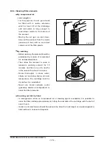
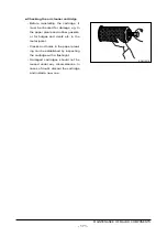
Page 173: ...m and a lug on the collector which should register Where the filter is installed horizontally watch for top mark on cleaner bowl 6 5 2 Changing filter element Caution Do not allow dirt to get into the clean air end On removing the hexagon nut take out the dirty cartridge and renew or clean Wipe the cleaner housing with a damp cloth in particular the sealing surface for the element 169 MAINTENANCE ...

Page 174: ... washing solvent for 10 minutes and then move it to and for in the solvent for about 5 minutes Rinse thoroughly in clean water shake out and allow drying at room temperature The cartridge must be dry before it is reinstalled Never use steam sprayers petrol gasoline alkalis or hot liquids etc to clean the filter elements Knocking out dirt by hand In emergencies when no compressed air or cleaning ag...

Page 175: ...er gaskets or for bulges and dents etc in the metal jacket Cracks and holes in the paper pleat ing can be established by inspecting the cartridge with a flashlight Damaged cartridges should not be reused under any circumstances In cases of doubt discard the cartridge and install a new one 171 MAINTENANCE OF MAJOR COMPONENTS EA6O5016 ...

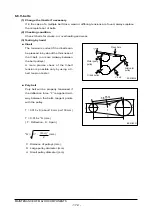
Page 176: ...y between the belt pulleys A more precise check of the V belt tension is possible only by using a V belt tension tester Poly belt Poly belt will be properly tensioned if the deflection force F is applied mid way between the belt s tangent points with the pulley T 0 015 x S about 1 5 mm per 100 mm T 0 015 x S mm T Deflection S Span S C2 mm 172 MAINTENANCE OF MAJOR COMPONENTS Water pump pulley Press...

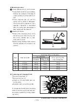
Page 177: ...he scale Before taking readings make ensure that the indicator arm remains in its position 5 Tensioning and changing V belt Remove fixing bolts 1 Remove lock nut 2 Adjust nut 3 until V belts have cor rect tensions Retighten lock nut and fixing bolts To change the V belts loosen mounting bolts 1 and lock nut 2 and push ten sion pulley inwards by turning adjust ing nut 3 2 1 173 MAINTENANCE OF MAJOR...

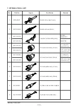
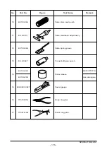
Page 178: ... Front 5 Oil seal insert ass y Rear 6 EF 123 052 Oil seal puller ass y Front 7 EF 123 048 Oil seal puller ass y Rear 8 EU 2 0531 Cylinder pressure tester adapter 9 EU 123 087 Cylinder liner puller ass y EF 123 015 EF 123 156 D2366 DE12 T TI DE12TIS EF 123 127 EF 123 173 CR made USA up to 2000 Apr NOK made Japan From 2000 may EF 123 053 EF 123 194 CR made USA up to 2000 Apr NOK made Japan From 2000...

Page 179: ...em seal punch 11 EU 2 0131 Valve clearance adjust ass y 12 EF 123 065 Valve spring press 13 EU 2 0647 Crankshaft gear punch 14 Piston sleeve 15 60 99901 0027 Feeler gauge 16 T7610001E Snap ring plier 17 T7621010E Piston ring plier EF 123 079 EF 120 208 DE12 T TI TIS Use all engine ...

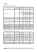
Page 180: ...kg m 1st 15 kg m Crankshaft main bearing cap bolt M16 B 1 5 12 9T 2nd 25 kg m 3rd 30 kg m Balance weight fixing bolt M14 B 1 5 10 9T 14 0 kg m Split type Flywheel fixing bolt M14 B 1 5 10 9T 18 0 kg m Crankshaft pulley fixing bolt M12 B 1 5 12 9T 13 4 kg m Oil spray nozzle M6 8 8T 1 0 kg m Major Parts Screw Strength Tightening Torque Remarks Diameter x pitch grade Injection nozzle holder nut M6 8 ...

Page 181: ... 83 0 78 1 2 1 3 1 4 1 95 2 35 M8 0 7 0 75 1 1 1 1 4 1 25 1 9 2 1 2 2 3 1 3 8 M8 B 1 0 73 0 8 1 2 1 1 1 5 1 34 2 1 2 3 2 4 3 35 4 1 M10 1 35 1 4 2 2 1 9 2 7 2 35 3 7 4 2 4 4 6 2 7 4 M10 B 1 1 5 1 6 2 5 2 1 3 1 2 8 4 3 4 9 5 7 8 4 M12 2 4 2 5 3 7 3 3 4 7 4 2 6 3 7 2 7 5 10 5 12 5 M12 B 1 5 2 55 2 7 4 3 5 5 4 6 6 8 7 7 8 11 2 13 4 M14 3 7 3 9 6 5 2 7 5 7 10 11 5 12 17 20 M14 B 1 5 4 1 4 3 6 6 5 7 8 ...

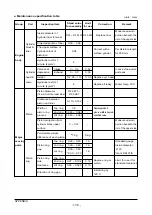
Page 182: ...ulic test for 1 4 Replace if leaky Water temp 70 C minute kg cm2 Piston diameter N122 873 18 mm from the lower side N122 887 Clearance between 0 113 0 152 piston and liner Width of Top ring 3 5 Replace piston if Piston piston ring 2nd ring 3 060 3 080 groove width is beyond grooves Oil ring 4 040 4 060 specified value Piston projection from Measure unworn cylinder block upper 0 0 12 portion beneat...

Page 183: ...ap bolt 30 Apply oil to bolt on bearing cap kg m install surface Measure by tightening Journal bearing crush 0 11 0 13 metal cap then Major loosening one stud bolt moving Oil seal for wear Replace oil seal Replace with new parts if oil leaking one use shim Clearance between con 0 049 0 119 0 20 Replace bearing rod bearing crank pin End play of con rod 0 22 0 319 0 5 Replace con rod crush Clearance...

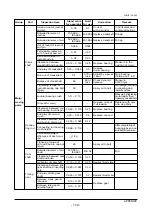
Page 184: ...de press in Clearance between valve Intake 22 guide vavle Exhaust 22 spring seat Free length 75 5 72 85 9 82 5 Valve Spring tension Intake set length 61 8 68 3 61 8 Valve valve 37 mm kg 74 4 82 4 74 4 system spring Straightness against free 1 0 2 0 length 1 5 Free length 65 61 75 76 4 72 Spring tension 36 1 39 9 36 1 Replace Mark DE12TIS set length 45 1 50 1 45 1 valve spring 34 mm kg Straightness...

Page 185: ...oil temperature 120 in short time C Axial play 0 055 0 105 of oil pump gear Replace gear Clearance between or cover gear shaft oil pump 0 032 0 068 cover hole Clearance between Replace bush drive gear shaft 0 040 0 082 or cover Oil cover hole pump Outside diameter N16 950 Replace gear N17e7 Lubricating of gear shaft N16 968 system Outside diameter N27 939 Replace bushing N28e7 of drive gear bushin...

Page 186: ... if defective Thermostat under atmospheric pressure Full opening temp C 95 or lower Stroke min 8mm Fuel pipe injection pipe nozzle holder for Correct or replace Piping damage cracks the looseness bad packing other Fuel filter element for Clean or replace damage Fuel Injection pressure of injection DE12T TI TIA 220 Adjust by shim DE12TIS 160 220 system nozzle kg cm2 Operating pressure of overflow 1...

Page 187: ... Engine Assembly DE12TIS ECIEA 183 APPENDIX EE6OM026 ...

Page 188: ......

Reviews: