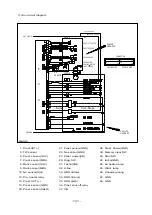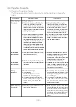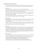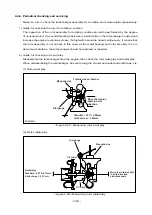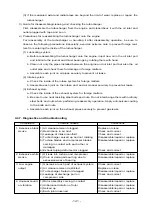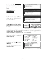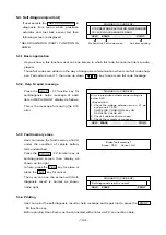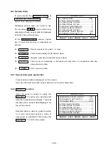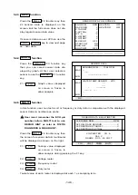
11) Ecu circuit diagram
- 131 -
KEY ON S/W
ENGINE
PREST. ACTUATOR
PREST. SENSOR
RACK SENSOR
PRE-HEATER
COOLING WATER
TEMP. SENSOR
NE
SENSOR
E
V
V
V
V
V
E
E
5A ECU POWER
PREST ACT. POWER
ENGINE
HARNESS
ENGINE SIDE
VEHICLE
HARNESS
VEHICLE SIDE
CONNECTOR
GROUND
E
K-Line
Scan-Scope
C
U
1
14
27
28
13
26
37
48
20A
14
19
20
1
6
7
VEHICLE
EA2M4031
1. Prest.ACT(-)
5. TW sensor
6. Prest. sensor(OSC)
7. Prest. sensor(MDL)
8. Rack sensor(OSC)
9. Rack sensor(MDL)
10. Ne sensor(SIG)
12. Pre. heater relay
14. Prest ACT.(+)
19. Prest. sensor(GND)
20. Prest. sensor(SHLD)
21. Prest. sensor(GND)
23. Ne sensor(GND)
27. Prest. power(VB)
29. Diag. SW
31. Tacho(SIG)
32. K-line
33. DDS 3(data)
34. DDS 3(clock)
35. DDS 3(stb)
36. Prest. shut off relay
37. VB
38. Prest. Power(GND)
39. Memory clear SW
40. Start SW
42. tacho(GND)
44. Air heater lamp
45. DIAG. lamp
46. Chassis groung
47. GND
48. GND


