


195
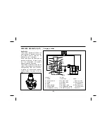
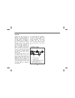
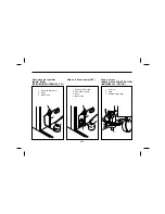
Mode of operation
When the pump is inoperative, cylin-
der(6) communicates via the feed ho-
les(5) with reservoir(2) containing the
antifreeze. When plunger rod(1) is
depressed, piston(4) moves down-
wards, closeing feed holes(5) and
causing approx. 1cm
3
of antifreeze to
be injected into the air stream, via
check valve(7). As long as plunger
rod(1) is in the operating position, the
further flow of fluid of from reser-
voir(2) is interrupted. When plunger
rod(1) and piston(4) are released,
they are moved back to their original
positions, due to the action of return
spring(3). Compression spring(8) clos-
es check valve(7), and cylinder(6) is
again filled with antifreeze through
feed holes(5). At any further stroke,
prior to setting off and with the com-
pressor in operation, appr. 1 cm
3
of
antifreeze per stroke is fed into the
air stream. Following any pump oper-
ation, several brake applications must
be made.
8
7
6
5
4
3
2
1
1
%
Plunger rod
2
%
Reservoir
3
%
Return sprng
4
%
Pump
5
%
Feed hole
6
%
Cylinder
7
%
Check valve
8
%
Compression spring
Summary of Contents for BH090
Page 220: ...218 Drag link RR 2 points For leaf spring Spring and shackle pin 12 points...
Page 255: ...253 BODY DIMENSION BM090 ROOF ON COOLER NON COOLER APPROX APPROX...
Page 256: ...254 BS090...
Page 259: ...257 ROOF ON COOLER SUB ENG COOLER NON COOLER APPROX APPROX BH115E...
Page 260: ...258 ROOF ON COOLER SUB ENG COOLER APPROX APPROX BH120E...


