ENGLISH
9
8.5
Connect pumps that are delivered without cable and/or plugs to an
external mains switch with a minimum contact gap of
0.12" (
3 mm
)
in all poles.
9. MAINTENANCE AND CLEANING
In normal operation, the pump does not require any specific maintenance, thanks to its mechanical seal lubricated in an oil chamber
and to its sealed-for-life bearings. The electropump must not be dismantled unless by skilled personnel in possession of the
qualifications required by the regulations in force. In any case, all repairs and maintenance jobs must be carried out only after having
disconnected the pump from the power mains.
During disassembly, pay attention to any sharp parts which could cause injury.
Checking and changing the sealing oil
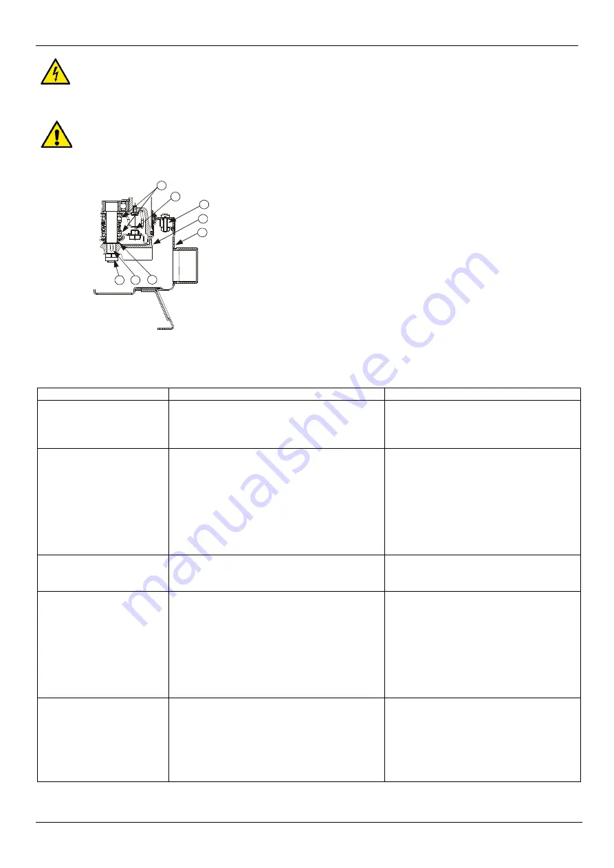
To perform this operation, slacken the six screws (45) so as to be able to remove the strainer
cover , the strainer and the pump body (1). Retain the O-ring (28) and the nuts (51). Using a
suitable spanner, unscrew the impeller retaining nut (18), holding the impeller (4) still with your
hand. Retain the key (17) and the sand guard (15). Now overturn the pump with the hydraulic
part facing upwards, unscrew and remove the drainage cap (64).
Tilt the pump so as to let the oil flow out of the drainage hole (64) and catch it in a container.
Analyse the oil: if you find any particles of water or abrasive materials (for example, sand) it is
advisable to check the condition of the mechanical seal (16) and to have it changed if
necessary (at a specialized centre). In this case change the oil too, with about
6oz
170 gr of oil type MARCOL 152ESSO.
Top up the oil level inside the sealing oil chamber using a special funnel inserted in the hole in
the cap (64). Screw the drainage cap (64) back on and perform the disassembly operations in
inverse order to reassemble the pump after having spread a suitable amount of teflon grease
in the seat of the sand guard (15).
OLD OIL MUST BE DISPOSED OF AS REQUIRED BY THE REGULATIONS IN FORCE.
10. TROUBLESHOOTING
FAULT
CHECK (possible cause)
REMEDY
1. The motor does not start and
makes no noise.
A. Check that the motor is live.
B. Check the protection fuses.
C. The float switch does not allow starting.
B. If they are burnt-out, change them.
C. -Ensure that the float moves freely.
-Ensure that the float is efficient (contact the
supplier).
2. The pump does not deliver.
A. The intake grid or the pipes are blocked.
B. The impeller is worn or blocked.
C. The check valve, if installed on the delivery pipe, is
blocked in closed position.
D. The level of the liquid is too low. When starting, the
level of the liquid must be higher than that of the
strainer.
E. The required head is higher than the pump
characteristics.
A. Remove the blockage.
B. Change the impeller or remove the blockage.
C. Check that the valve is operating correctly and
replace it if necessary.
D. Adjust the length of the float switch cable
(SEE THE PARAGRAPH ON "ADJUSTING
THE FLOAT SWITCH").
3. The pump does not stop.
A. The switch is not disactivated by the float.
A. -Ensure that the float moves freely.
B. -Check float efficiency (the contacts could be
damaged - contact the supplier).
4. The flow is insufficient.
A. Ensure that the intake grid is not partly blocked.
B. Ensure that the impeller or the delivery pipe are not
partly blocked or encrusted.
C. Ensure that the impeller is not worn.
D. Ensure that the check valve (if fitted) is not partly
clogged.
E. On three-phase motors, check that the direction of
rotation is correct (See the paragraph on
"CHECKING THE DIRECTION OF ROTATION").
A. Remove any blockage.
B. Remove any blockage.
C. Change the impeller.
D. Carefully clean the check valve.
E. Invert the connection of two supply wires.
5. The thermal overload
protection stops the pump.
A. Check that the liquid to be pumped is not too dense
as this could cause overheating of the motor.
B. Check that the water temperature is not too high.
C. The pump is partly blocked by impurities.
D. The pump is mechanically blocked.
C. Carefully clean the pump.
D. Check whether there is rubbing between the
moving and fixed parts; check the wear of the
bearings (contact the supplier).
18
17
15
1
4
45
64
16
Fig.5
Summary of Contents for FEKA VS
Page 9: ......


