background image

ENGLISH

GB

14

Never insulate the electronic control device.

- In the case of maintenance, always use a set of new gaskets.

5.2  Rotation of the Motor Heads

If the circulator is installed on pipes in a horizontal position, it will be necessary to rotate 

the motor with the respective electronic device through 90 degrees in order to maintain 

the grade of IP protection and to allow the user a more convenient interaction with the 

graphic interface (see Figure 2-3).

Before rotating the circulator, ensure that it has been completely drained.

Should it be necessary to rotate the motor heads, follow the instructions below with care 

to ensure correct installation:

1. 

Unscrew the 4 screws fixing the motor assembly to the pump body (figure A).

2. 

Rotate the motor assembly keeping it in the seat where it couples with the pump 

body (figure A-B).

3. 

Once the head has been rotated into the desired position, tighten the 4 screws, 

always proceeding in cross formation (figure C).

If the motor assembly has been removed from its seat, pay the greatest attention during 

assembly, taking care to insert the impeller completely in the floating ring before tighten

-

ing the retaining screws (figure D). If it has been correctly assembled, the motor assembly 

rests completely on the pump body.

Incorrect assembly may damage the impeller, causing a typical rubbing 

noise when the circulator starts.

T

he electronic control device must always remain in vertical position!

Ensure that the connecting cable of the pressure sensor never comes in 

contact with the motor casing.

5.3  Non-return valve

If the system is equipped with a non-return valve, ensure that the minimum pressure of 

the circulator is always higher than the valve closing pressure.

6.  ELECTRICAL CONNECTIONS

The electrical connections must be made by expert, qualified personnel.


-

The circulator does not require any external motor protection.


-

Ensure that the supply voltage and frequency are the same as the values indicated on 

the electrical data plate of the circulator.

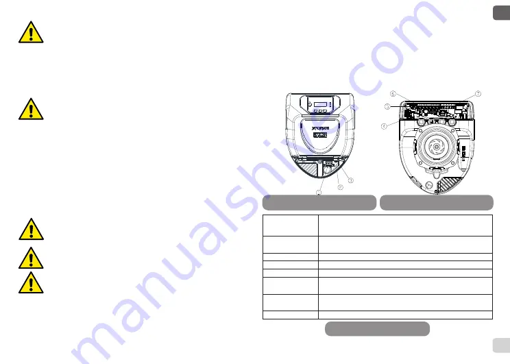
Figure 4: Electrical connections (front)

Figure 5: Electrical connections (rear)

Reference

(Figure 4 and Figure 5)

Description

1

Pull-out terminal board for connection of the supply line:

1x220-240 V, 50/60 Hz

2

auxiliary LED

3

system live indicating LED

4

Connector for connecting twin circulators

5

Connector for connecting the fluid pressure and temperature sen

-

sor (standard)

6

Pull-out 13-pole terminal board for connecting the inputs and the 

MODBUS systems

7

Pull-out 6-pole terminal board for alarm signals and system status

Table 1 Electrical connections

Summary of Contents for EVOPLUS B 120/220.32 M

Page 1: ...INSTRUCTIONS FOR INSTALLATION AND MAINTENANCE V3 0...

Page 2: ...40 50 M D 60 240 50 M D 80 240 50 M D 100 280 50 M D 120 280 50 M D 150 280 50 M D 180 280 50 M B 40 340 65 M B 60 340 65 M B 80 340 65 M B 100 340 65 M B 120 340 65 M B 150 340 65 M B 40 340 65 SAN M...

Page 3: ...1A ONLY FOR HEATING Figure 1 Assembly position 1 2 4 3 Torque 19 20 Nm C D Figure 2 Instructions for motor head assembly 3 B 1 2 A Figure 10 Control panel Figure 3 Installation on horizontal pipes...

Page 4: ...B 180 280 50 SAN M 18 0 37 02 D 180 280 50 M 18 0 66 64 B 40 340 65 M B 40 340 65 SAN M 4 0 27 90 D 40 340 65 M 4 0 50 22 B 60 340 65 M B 60 340 65 SAN M 6 0 34 47 D 60 340 65 M 6 0 62 05 B 80 340 65...

Page 5: ...8 EVOPLUS B 80 450 100 M 0 18 EVOPLUS B 100 450 100 M 0 19 EVOPLUS B 120 450 100 M 0 19 EVOPLUS D 120 220 32 M 0 22 EVOPLUS D 40 220 40 M 0 23 EVOPLUS D 60 220 40 M 0 23 EVOPLUS D 80 220 40 M 0 23 EVO...

Page 6: ......

Page 7: ......

Page 8: ...9 Control Panel 18 9 1 Graphic Display 18 9 2 Navigation Buttons 18 9 3 Warning Lights 18 10 Menus 18 11 Factory settings 20 12 TypeS of Alarm 21 13 Error Condition And Reset 21 INDEX OF FIGURES Figu...

Page 9: ...jecting the products to needless impacts and collisions To lift and transport the circulator use lifting devices with the aid of the pallet supplied with it if contemplated 4 3 Weight The adhesive pla...

Page 10: ...it has been correctly assembled the motor assembly rests completely on the pump body Incorrect assembly may damage the impeller causing a typical rubbing noise when the circulator starts The electron...

Page 11: ...e pump in re mote mode 13 IN2 10 Clean contact Economy If is activated from the control panel see par 12 Page 5 0 of the EVO PLUS menu it will be possible to active the set point reduction function in...

Page 12: ...d 5 COM 6 NO The outputs OUT1 and OUT2 are available on the pull out 6 pole terminal board as spec ified in Table 4 which also shows the type of contact NC Normally Closed COM Common NO Normally Open...

Page 13: ...gh temperature and pressure the fluid in the sys tem may also be in the form of steam DANGER OF SCALDING It is dangerous to touch the circulator DANGER OF SCALDING Once all the electrical and hydrauli...

Page 14: ...duction of the circu lator performance is ensured depending on the lowering of the temperature of the circulating liq uid when the demand for heating is lower Plants with constant flow single pipe and...

Page 15: ...h set point set by external signal 0 10V or PWM 6 Constant differential pressure regulation with set point depending on temperature 7 Regulation with constant curve with rotation speed set from the di...

Page 16: ...ial pressure regulation THs 50 C Operating mode auto Set point reduction percentage 50 Type of external analogue signal 0 10V Twin operating mode Alternate every 24h Pump start control EXT from remote...

Page 17: ...the system again If the error persists change the circulator e37 Low mains voltage LP Switch off system power Wait for the warning lights on the control panel to go off then power the system again Ch...

Page 18: ...ystem power Wait for the motor to cool down Power the system again e57 e58 f 100 Hz f 5 kHz Check that the PWM external signal is operating and connected as specified Energy Efficiency Index EEI The b...

Page 19: ...tgroup com Tel 31 416 387280 Fax 31 416 387299 DAB PUMPS B V tHofveld 6 C1 1702 Groot Bijgaarden Belgium info belgium dwtgroup com Tel 32 2 4668353 DAB PUMPS IBERICA S L Calle Verano 18 20 22 28850 To...

Reviews: