


The diagram below display a typical end node connected to the Switch.
Figure 24. Switch to End Node
Switch Management
Command Line Interface (CLI)
The CLI provides access to all of the software features available on the Switch. These features can be
enabled, configured, disabled, or monitored by simply entering the appropriate command after the CLI
prompt and pressing the Enter key. The Console port offers an Out-Of-Band (OOB) connection to the CLI
and the LAN ports offers an in-band connection to the CLI using Telnet or SSH.
Connecting to the Console Port
The Console port is used to connect to the CLI of the Switch. Connect the DB9 connector of the console
cable (included in the packaging) to the Serial (COM) port of the computer. Connect the RJ45 connector of
the console cable to the Console port on the Switch.
To access the CLI through the Console port,
Terminal Emulation Software
must be used like
PuTTY
or
Tera
Term
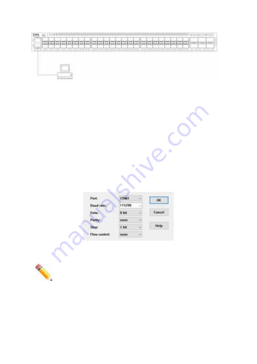
. The Switch uses a connection of
115200
bits per second with
no flow control
enabled.
Figure 25. Console Connection Settings
After the boot sequence completed, the CLI login screen is displayed.
NOTE:
The default username and password for the CLI and Web UI is
admin
.
Logging into the CLI
At the login screen, enter the Username and Password and press
Enter
after each entry to access the CLI.
15
Summary of Contents for DXS-3610-54S
Page 20: ...DXS 3610 54S DXS 3610 54S 2 AC DXS PWR700AC 5 DXS FAN200 AC RJ45 RS 232 USB 4 2 20...
Page 24: ...5 DXS 3610 54S 6 24...
Page 25: ...19 DXS 3610 54S 19 7 8 9 25...
Page 26: ...10 DGS 3610 54S QSFP28 SFP QSFP QSFP28 100GE QSFP28 11 QSFP QSFP28 QSFP28 26...
Page 27: ...SFP SFP 10GE SFP 12 SFP SFP SFP AC DXS 3610 54S AC 27...
Page 28: ...13 AC 14 AC PSU 2 AC AC 100 240 50 60 DC DXS 3610 54S DC 28...
Page 29: ...15 DC 16 DC PSU 2 DC DC 48 5 2 A 17 DC DC 29...
Page 30: ...DGS 3610 54S DXS FAN200 18 19 30...
Page 31: ...DXS 3610 54S 12 IP Telnet Web RJ45 SFP QSFP28 SNMP 20 21 31...
Page 38: ...38...


