background image

34

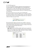
6.6.2. EDID Creator


Select: 

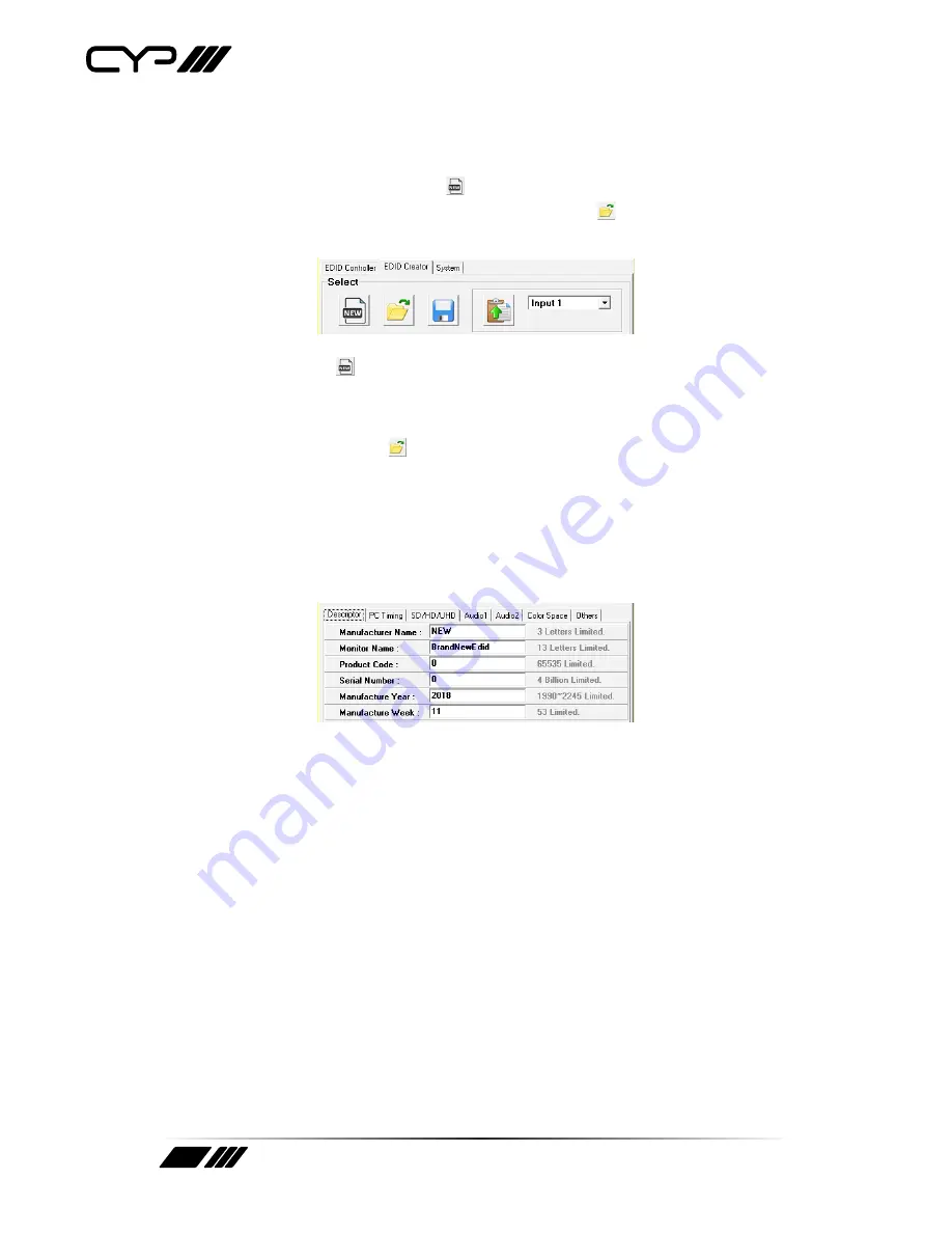
Click on the “EDID Creator” tab to begin designing a new EDID 

from scratch (select the “New”   icon), to modify an existing EDID 

stored on the PC as a *.bin file (select the “Load”   icon) or to edit an 

EDID copied from the unit via the EDID Analyser’s edit option.


-

Selecting “New”   will automatically populate the various EDID fields 

with basic information that can be easily edited to match the user’s 

preferences.


-

Clicking on the “Load”   icon will open a file load window and after 

the *.bin file has been selected and loaded the EDID fields will be 

populated with the information from that file. The same will happen 

when the EDID is copied from the “EDID Analyser” window.


Edit: 

The following tabs provide access to a wide range of EDID 

information which can be edited:


-

Descriptor: 

This tab allows for the editing of various description and 

information fields within the EDID file such as Manufacturer Name, 

Monitor Name, etc.


-

PC Timing & SD/HD/UHD: 

These tabs allow for the selection of the 

resolutions and refresh rates that the EDID will report as supported.


-

Audio1 & Audio2: 

These tabs allow for the selection of which audio 

formats, audio frequencies, channels and speaker locations are 

supported.


-

Colour Space: 

This tab allows for the selection of which colour 

formats and bit depths are supported, including BT.2020 and HDR 

support options.


-

Others: 

This tab contains options for supporting 3D and defining the 

CEC Address.

Summary of Contents for QU-28S-4K22

Page 1: ...QU 28S 4K22 2 to 8 HDMI Distribution Amplifier 4K HDCP2 2 HDMI2 0 OPERATION MANUAL ...

Page 2: ......

Page 3: ...rves the right to make improvements to this document and or product at any time and without notice COPYRIGHT NOTICE No part of this document may be reproduced transmitted transcribed stored in a retrieval system or any of its part translated into any language or computer file in any form or by any means electronic mechanical magnetic optical chemical manual or otherwise without express written per...

Page 4: ...to this product Never push an object of any kind into this product through any openings or empty slots in the unit as you may damage parts inside the unit Do not attach the power supply cabling to building surfaces Use only the supplied power supply unit PSU Do not use the PSU if it is damaged Do not allow anything to rest on the power cabling or allow any weight to be placed upon it or any person...

Page 5: ... 7 5 Features 7 6 Operation Controls and Functions 8 6 1 Front Panel 8 6 2 Rear Panel 9 6 3 OSD Menu 10 6 4 RS 232 Control 20 6 5 RS 232 Commands 21 6 6 EDID Management 32 7 Connection Diagram 36 8 Specifications 37 8 1 Technical Specifications 37 8 2 Video Specifications 38 9 Acronyms 43 ...

Page 6: ...allows the unit to function as two independent 1 4 splitters When Group Mode is enabled each of the 2 HDMI inputs are routed to their own discrete set of 4 outputs When a mixture of displays with different specifications are connected each output can be configured to scale 4K to 1080p or apply colour space conversion 4 4 4 to 4 2 0 as appropriate Support for the CEC active source command to period...

Page 7: ...cial Group Mode allows the unit to function as two independent 1 4 splitters in a single box Supports current 10 bit and 12 bit HDR High Dynamic Range formats Supports pass through of LPCM 7 1 Bitstream and advanced HD Bitstream audio formats Per output selectable 4K to 1080p down scaling colour space conversion 4 4 4 to 4 2 0 Independent HDCP management engine for each output ensures stable perfo...

Page 8: ...will blink after any button press 2 MENU Press to enter the OSD menu or to back out from menu items Note Press and hold the MENU button for 3 seconds while connecting the power supply to reset all settings to the factory defaults 3 IN 1 Press to move down or adjust selections within OSD menus When not in the OSD menu press this button to switch to Input 1 Note Pressing MENU and together will force...

Page 9: ... 2 3 4 5 1 OUT E H Connect to HDMI TVs monitors or amplifiers for digital video and audio output Note When Group Mode is active these outputs will display Input 2 2 IN 2 Connect to HDMI source equipment such as a media player game console or set top box 3 SERVICE This port is reserved for firmware update use only 4 RS 232 Connect directly to a PC laptop or other serial control device with a 3 pin ...

Page 10: ...N MENU Input Switch Input Information Output 4K Converter Output Information EDID Control HDCP Control CEC Control Remote Control OSD Setting System Setting The individual functions of the OSD will be introduced in the following section Items marked in BOLD are the factory default settings MAIN MENU LEVEL 2 LEVEL 3 Input Switch Switch to INPUT 1 Input 2 Auto Switch On OFF Group Mode On OFF 1 Switc...

Page 11: ...es will provide this information 2 Name Show the current input s product name based on the source s info frame data Note Not all devices will provide this information 3 Fmt Show the video format of the current input 4 Reso Show the resolution and framerate of the current input 5 Freq Show the signal frequency of the current input 6 Depth Show the colour bit depth of the current input 7 Colour Show...

Page 12: ... Out A H Sets the 4K conversion mode to use for each output individually Note 4K conversion is only available with 4K sources Due to a chipset limitation 4K sources using the 4 2 2 colour space may display with incorrect colours when scaled to 1080p MAIN MENU LEVEL 2 LEVEL 3 Output Information Out A H Output Details 1 Out A H Show the connection status resolution and framerate for each output MAIN...

Page 13: ... A Copy Out B Copy Out C Copy Out D Copy Out E Copy Out F Copy Out G Copy Out H In 2 INT FHD 2CH Int FHD MCH Int UHD 2CH Int UHD MCH Int UHD 2CH Int UHD MCH Int HDR 2CH Int HDR MCH User 1 User 2 Copy Out A Copy Out B Copy Out C Copy Out D Copy Out E Copy Out F Copy Out G Copy Out H ...

Page 14: ...g the output for a couple seconds 3 Vndr Show the vendor name from the EDID used with the current Input 4 Name Show the monitor name from the EDID used with the current Input 5 Reso Show the maximum supported resolution from the EDID used with the current Input 6 Freq Show the maximum supported frequency from the EDID used with the current Input 7 Depth Show the maximum supported bit depth from th...

Page 15: ...ntrol Auto Active On OFF Auto Standby On OFF Out A H CEC Address Informa tion 1 Auto Active Enable or disable sending the CEC active source command to connected displays every 10 minutes Note The connected display must support the CEC active source command 2 Auto Standby Enable or disable sending the CEC standby command to connected displays if there has been no live input source detected for more...

Page 16: ...nit s OSD menu using the remote s red green yellow and blue buttons by assigning them to the functions of the unit s front panel MENU MINUS PLUS and ENTER buttons Note Requires a compatible remote control and display 2 Hot Key Enables or disables support for the additional front panel hot key functionality that is used when not in the OSD IN 1 IN 2 and GROUP 3 Button and Hot Key Assignment Lists h...

Page 17: ...out Never 1 60 30 Horizontal 0 100 2 Vertical 0 100 3 Transparency 0 7 3 Contrast 0 1 0 Panel Colour Red Green Blue GRAY OSD Setting Font Colour Black White Red Green BLUE Yellow Cyan Magenta Free Run No Red Green BLUE Black Colour Default NO Yes ...

Page 18: ...menu s transparency level 5 Contrast Set the OSD menu contrast mode 6 Panel Colour Set the OSD menu s panel colour 7 Font Colour Set the OSD menu s font colour 8 Free Run Set the Free Run colour to display when no source is detected Selecting Colour will show a colour bar pattern Selecting No will disable the Free Run function 9 Default Reset the OSD configuration settings to their factory default...

Page 19: ...dor ID 2 PID Show the unit s Product ID 3 SN Show the unit s Serial Number 4 FW Ver Show the unit s current firmware version 5 Factory Reset Reset the unit s configuration to the factory defaults 6 Software Control Enable or disable RS 232 support for connecting to the EDID Management Software See section 6 6 Note Enabling this function will disable normal RS 232 control of the unit ...

Page 20: ...20 6 4 RS 232 Control UNIT PC SERIAL PORT SETTINGS Pin Pinout Pin Pinout Baud Rate 19200 1 Data Bits 8 1 Tx 2 Rx Parity Bit None 2 Rx 3 Tx Stop Bits 1 4 Flow Control None 3 GND 5 GND 6 7 8 9 ...

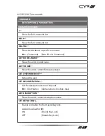
Page 21: ...nd GET MODEL NAME Show the unit s model name GET FW VER Show the unit s current firmware version SET SYSTEM REBOOT Reboot the unit SET DESCRIPTION N1 Set the description name of the unit N1 Unit Name Alphanumeric 64 chars max GET DESCRIPTION Show the unit s current description name SET KEYLOCK N1 Enable or disable the front panel key lock Available values for N1 ON Enable Key Lock OFF Disable Key ...

Page 22: ...nput Commands GET IN PORT NUMBER Report the number of inputs supported by the unit GET IN TYPE LIST List the video format supported by each Input GET IN N1 FORMAT Show Input N1 s video format N1 1 2 Input Port Valid response values are 0 Not Active 1 DVI Mode 2 HDMI Mode GET IN N1 Colour SPACE Show Input N1 s current colour space N1 1 2 Input Port Valid response values are 0 Not Active 1 RGB 2 YUV...

Page 23: ... bit 12 12 bit 16 16 bit GET IN N1 TIMING Show Input N1 s current resolution and timing N1 1 2 Input Port Note Only works with a currently displayed Input SET IN N1 HDCP MODE N2 Set Input N1 s HDCP mode to N2 N1 1 2 Input Port Available settings for N2 0 Apple Mode 1 Refer to Source 2 Refer to Sink GET IN N1 HDCP MODE Get Input N1 s current HDCP mode N1 1 2 Input Port ...

Page 24: ... N2 Assign EDID N2 to be used with Input N1 N1 1 2 Input Port Available values for N2 1 Int FHD 2CH 2 Int FHD Multi CH 3 Int UHD 2CH 4 Int UHD Multi CH 5 Int UHD 2CH 6 Int UHD Multi CH 7 Int HDR 2CH 8 Int HDR Multi CH 9 User EDID 1 10 User EDID 2 11 Copy Output A 12 Copy Output B 13 Copy Output C 14 Copy Output D 15 Copy Output E 16 Copy Output F 17 Copy Output G 18 Copy Output H ...

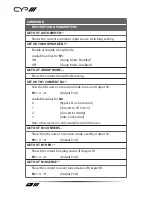
Page 25: ... Output Commands GET OUT PORT NUMBER Report the number of outputs supported by the unit GET OUT TYPE LIST Show the video format supported by each output SET OUT ROUTE N1 Route Input N1 to all Outputs N1 1 2 Input Port Note Setting this will disable Group Mode GET OUT ROUTE Show the current video routing source SET OUT AUTO SWITCH N1 Enable or disable automatic input source switching Available valu...

Page 26: ...ONVERT N2 Sets the 4K source conversion mode to use on Output N1 N1 A H Output Port Available values for N2 0 Bypass No Conversion 1 Convert to YUV 4 2 0 2 Convert to 1080p 3 Auto Conversion Note 4K conversion is only available with 4K sources GET OUT N1 CONVERT Show the 4K source conversion mode used by Output N1 N1 A H Output Port GET OUT N1 HPD Show the current hot plug status of Output N1 N1 A...

Page 27: ...the EDID read from Output N1 N1 A H Output Port GET OUT N1 EDID INFORMATION Show a description of the EDID read from Output N1 N1 A H Output Port User EDID Commands GET USER EDID NUMBER Show the number of User EDIDs supported by the unit SET USER N1 EDID DATA N2 Update the contents of User EDID N1 with new raw hex data N1 1 2 User EDID Number N2 Hex Data Raw EDID Hex Data GET USER N1 EDID DATA Sho...

Page 28: ... the current OSD timeout value SET OSD HORIZONTAL N1 Set the OSD menu s horizontal position N1 0 100 Horizontal Position GET OSD HORIZONTAL Show the OSD menu s current horizontal position N1 0 100 Vertical Position SET OSD VERTICAL N1 Set the OSD menu s vertical position GET OSD VERTICAL Show the OSD menu s current vertical position SET OSD TRANSPARENCY N1 Set the OSD menu s transparency level Ava...

Page 29: ... 1 Low Contrast GET OSD CONTRAST Show the OSD menu s current contrast level SET OSD PANEL Colour N1 Set the OSD menu s background colour Available values for N1 1 Red 2 Green 3 Blue 4 Gray GET OSD PANEL Colour Show the OSD menu s current background colour SET OSD FONT Colour N1 Set the OSD menu s font colour Available values for N1 1 Black 2 White 3 Red 4 Green 5 Blue 6 Yellow 7 Cyan 8 Magenta ...

Page 30: ...lable values for N1 0 Free Run Disabled 1 Red 2 Green 3 Blue 4 Black 5 Colour Bars GET OSD FREERUN Colour Show the current Free Run colour setting CEC Commands SET CEC AUTO ACTIVE N1 Enable or disable sending the CEC active source command to connected displays every 10 minutes Available values for N1 ON Enable Active Source OFF Disable Active Source Note The connected display must support the CEC ...

Page 31: ... The connected display must support the CEC standby command GET CEC AUTO STANDBY Show the current CEC Auto Standby setting SET CEC REMOTE LINK N1 Select the display output to accept CEC remote control commands from to control the unit or disable the feature Available values for N1 OFF Disable Feature A H Enabled Output Port Note Requires a compatible remote control and display GET CEC REMOTE LINK ...

Page 32: ...ully completed an icon for it will appear on the windows desktop Launch the software by double clicking on the icon and the EDID Management device detection window will open up on your screen After launching the software power the unit on and then connect it to the PC laptop using an RS 232 cable Click on the Search button and any detected units will be displayed in the list Clicking on a detected...

Page 33: ...re uploaded into any of the User EDID slots by selecting the User EDID to replace from the dropdown and then clicking the Upload icon Before accepting the upload the software will check and verify that the EDID s header and checksum values are acceptable Analysis To analyse any EDID stored within the unit select the EDID to view from the dropdown and click on the Analysis icon From the Analyser wi...

Page 34: ...same will happen when the EDID is copied from the EDID Analyser window Edit The following tabs provide access to a wide range of EDID information which can be edited Descriptor This tab allows for the editing of various description and information fields within the EDID file such as Manufacturer Name Monitor Name etc PC Timing SD HD UHD These tabs allow for the selection of the resolutions and ref...

Page 35: ...ectly to the unit using the Save and Upload icons respectively 6 6 3 System Configuration Firmware Select the System tab to edit the software s description select the Rename icon to reset the unit to factory defaults select the Reset icon and to view the unit s current hardware and firmware version information ...

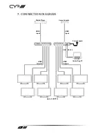
Page 36: ...R UHD 2X8 HDMI SPLITTER IN 1 GROUP 1 OUT A OUT B OUT C OUT D SERVICE RS 232 POWER DC 5V R T GROUP 2 IN 2 OUT H OUT G OUT F OUT E Power Supply RS 232 USB Up to 8 UHDTVs Media Player HDMI Input HDMI Outputs HDMI Outputs HDMI Input Game Console RS 232 Controlling PC ...

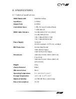
Page 37: ...p 60Hz 12 bit 15m 1080p 60Hz 8 bit Power Supply 5V 3A DC US EU standards CE FCC UL certified ESD Protection Human Body Model 8kV Air Discharge 4kV Contact Discharge Dimensions 240mm 24mm 103mm W H D Case Only 240mm 25mm 103mm W H D All Inclusive Weight 616g Chassis Material Metal Silkscreen Colour Black Operating Temperature 0 C 40 C 32 F 104 F Storage Temperature 20 C 60 C 4 F 140 F Relative Humi...

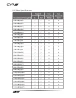
Page 38: ... In Out 640 480p 60 640 480p 72 640 480p 75 640 480p 85 720 400p 70 720 400p 85 720 480i 59 720 480i 60 720 480p 59 720 480p 60 720 576i 50 720 576p 50 800 600p 56 800 600p 60 800 600p 72 800 600p 75 800 600p 85 848 480p 60 1024 768p 60 1024 768p 70 1024 768p 75 1024 768p 85 1152 864p 70 1152 864p 75 ...

Page 39: ...1280 720p 24 1280 720p 25 1280 720p 29 1280 720p 30 1280 720p 50 1280 720p 59 1280 720p 60 1280 768p 60 1280 768p 60 RB 1280 768p 75 1280 768p 85 1280 800p 60 1280 800p 60 RB 1280 800p 75 1280 800p 85 1280 960p 60 1280 960p 85 1280 1024p 60 1280 1024p 75 1280 1024p 85 1360 768p 60 1366 768p 60 RB 1366 768p 60 ...

Page 40: ...00p 60 1440 900p 60 RB 1440 900p 75 1600 900p 60 RB 1600 1200p 50 1600 1200p 60 1600 1200p 65 1600 1200p 70 1600 1200p 75 1600 1200p 85 1680 1050p 60 1680 1050p 60 RB 1920 1080p 23 1920 1080p 24 1920 1080p 25 1920 1080p 29 1920 1080p 30 1920 1080p 50 1920 1080p 59 1920 1080p 60 1920 1080i 50 1920 1080i 59 1920 1080i 60 ...

Page 41: ...1080p 29 2048 1080p 30 2048 1080p 50 2048 1080p 59 2048 1080p 60 3840 2160p 23 4 2 2 3840 2160p 24 4 2 2 3840 2160p 25 4 2 2 3840 2160p 29 4 2 2 3840 2160p 30 4 2 2 3840 2160p 50 4 2 0 3840 2160p 59 4 2 0 3840 2160p 60 4 2 0 3840 2160p 23 4 4 4 3840 2160p 24 4 4 4 3840 2160p 25 4 4 4 3840 2160p 29 4 4 4 3840 2160p 30 4 4 4 3840 2160p 50 4 4 4 3840 2160p 59 4 4 4 ...

Page 42: ...0p 23 4 2 2 4096 2160p 24 4 2 2 4096 2160p 25 4 2 2 4096 2160p 29 4 2 2 4096 2160p 30 4 2 2 4096 2160p 50 4 2 0 4096 2160p 59 4 2 0 4096 2160p 60 4 2 0 4096 2160p 23 4 4 4 4096 2160p 24 4 4 4 4096 2160p 25 4 4 4 4096 2160p 29 4 4 4 4096 2160p 30 4 4 4 4096 2160p 50 4 4 4 4096 2160p 59 4 4 4 4096 2160p 60 4 4 4 ...

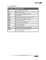
Page 43: ...tification Data HD High Definition HDCP High bandwidth Digital Content Protection HDMI High Definition Multimedia Interface HDR High Dynamic Range LPCM Linear Pulse Code Modulation UHD Ultra High Definition USB Universal Serial Bus VGA Video Graphics Array 640 480 60Hz WUXGA Wide Ultra Extended Graphics Array 1920 1200 60Hz ...

Reviews: