8
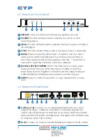
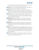
range of remotely located devices. Ensure that the remote being
used is within direct line-of-sight of the IR Extender.
3
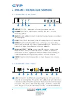
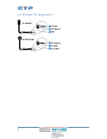
IR OUT:
Connect to the provided IR Blaster to transmit IR signals to
devices within direct line-of-sight of the IR Blaster.
4
RS-232:
Connect to the device you wish to control via a 3-pin
adapter cable to receive RS-232 commands from the Transmitter.
For sending commands to the Transmitter side, depending on your
equipment’s pinout, the Tx and Rx pins might need to be reversed.
5
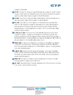
OPT. IN:
Connect to the optical audio output of a device such
as a media player or game console using an appropriate optical
cable. The audio will be sent back to the Transmitter via the OAR
(Optical Audio Return) feature.
6
HDMI OUT A~B:
Connect to HDMI TVs, monitors or amplifiers for
digital video and audio output. The selected output resolution
can be different for each HDMI port. A test pattern can also be
displayed.
7
AUDIO OUT:
Connect to powered speakers, an audio amplifier,
mixer, or DSP for balanced stereo analog output extracted from
an HDMI source with LPCM 2.0 audio. (Follows balanced audio
specifications.)
8
LAN:
Connect to an Ethernet supporting device or to your local
network as appropriate. The yellow LED will illuminate to indicate a
successful LAN connection between the Transmitter and Receiver,
however, if the yellow LED blinks irregularly it indicates a data link
error. The green LED will illuminate when the connected Ethernet
speed is 100Mbit/s.
9
DC 5V:
Plug the 5V DC power adapter into the unit and connect
it to an AC wall outlet for power. (Not required if the unit is being
powered by a 48V PoH Transmitter.)
Summary of Contents for CSC-6012RX
Page 2: ......
Page 40: ...CYPRESS TECHNOLOGY CO LTD www cypress com tw ...


