


Cygnus 4+ Operating Manual
M5-CYG4P-M-01_Iss5.doc
80
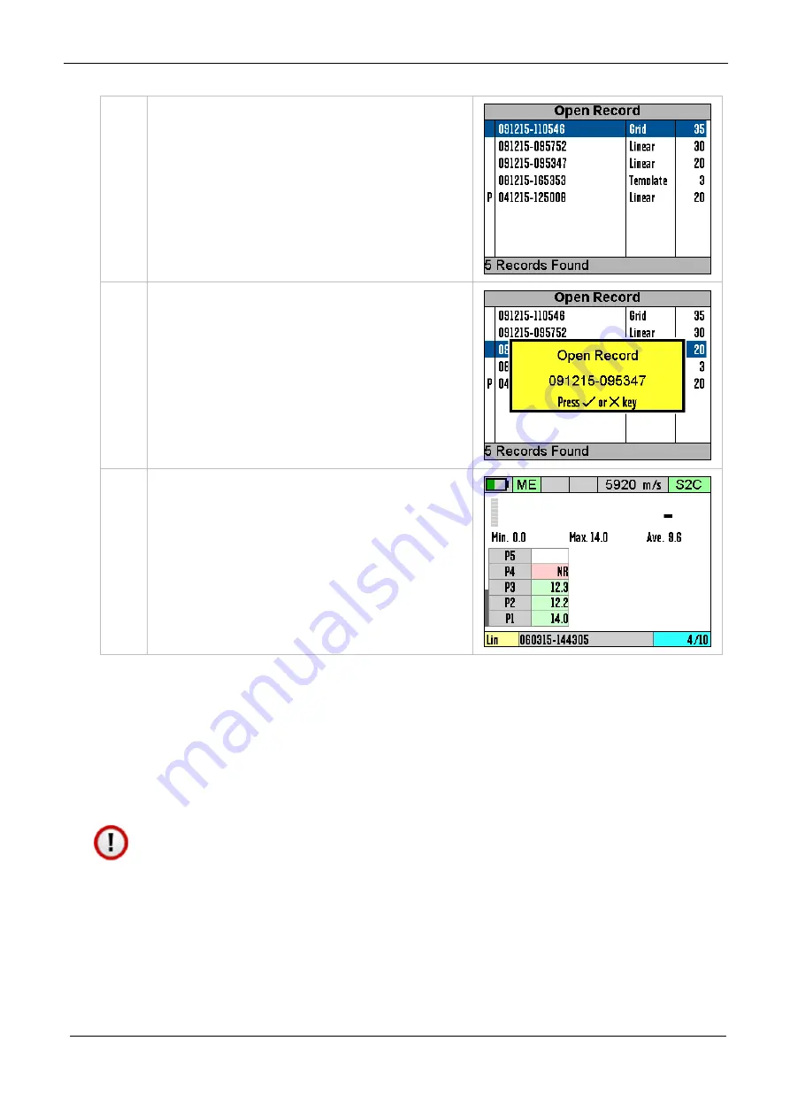
2.
Select the Record to open, the
most recent is at the top of the
list.
Confirm by pressing the √ key.
3.
Confirm by pressing the √ key.
4.
The record has been opened and
data logging record has been
resumed.
Protecting a Record
If you want to Protect a record from being deleted or modified
then you can use the Protect Record feature. Once protected
records cannot be deleted from the gauge and they cannot be re-
opened and amended or changed.
Once you protect a record then you will be unable to un-
protect the record from the gauge. You can however remove
the SD card and deleted the record files from the SD card
using a computer.


