


Chapter 2 Installation Instruction
20
SM 180-600 KMFX User Manual
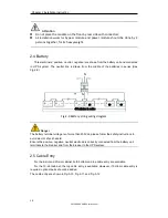
Battery
Cables crimped
OT terminal
M12
13mm
22Nm
Output
Cables crimped
OT terminal
M12
13mm
22Nm
PE
Cables crimped
OT terminal
M12
13mm
22Nm
20-slot cabinet
Main Input
Cables crimped
OT terminal
M16
17mm
96Nm
Bypass Input
Cables crimped
OT terminal
M16
17mm
96Nm
Battery
Cables crimped
OT terminal
M16
17mm
96Nm
Output
Cables crimped
OT terminal
M16
17mm
96Nm
PE
Cables crimped
OT terminal
M12
13mm
22Nm
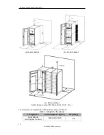
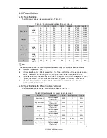
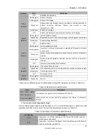
2.6.3 Circuit Breaker
The circuit breakers (CB) for the system are recommended in Table 2.4.
Table 2.4 Recommended CB
Installed position
6-slot cabinet
10-slot cabinet
20-slot cabinet
Input CB
300A/3P
600A/3P
/
Bypass Input CB
250A/3P
500A/3P
/
Output CB
250A/3P
500A/3P
/
Battery CB
400A,500Vdc
800A,500Vdc
1250A,500Vdc
For the 20-slot cabinet, the Main Input, Bypass Input and Output CB are installed in the
Cabinet.
Attention
The CB with RCD (Residual Current Device) is not suggested for the system.
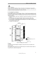
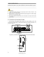
2.6.4 Connecting Power Cables
The steps of connecting power cables are as follows:
1. Verify that all the switches of the UPS are completely open and the UPS internal
maintenance bypass switch is open. Attach necessary warning signs to these switches to
prevent unauthorized operation.
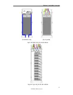
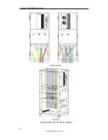
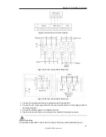
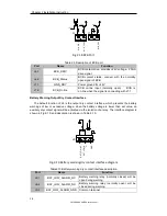
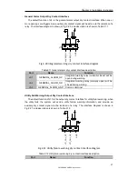
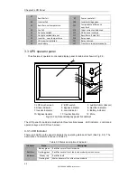
2. Open the back door of the cabinet, remove the plastic cover. The input and output
terminal, battery terminal and protective earth terminal are shown in Fig.2-11 &Fig 2.13.
Summary of Contents for SM180KMFX
Page 2: ...Ver 1 0 2 ...


