background image


Super Saver Bunsen Jet Brooder with SPI 

9


6. 

Installation 

Installation of your assembled brooder involves two steps: 

1.


Hanging the Unit 

2.


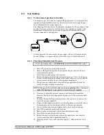
Gas Tube Hookup 

 
First we have an example drawing of how to hang the unit, then the next section covers gas 
hookup, including checking that the gas supplied to the unit is at the correct pressure. 
Remember to follow all safety precautions when hanging the unit, and hooking up the gas supply. 

6.1. 

Hanging the Unit 

6.1.1.


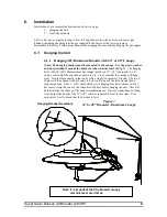
Hanging SPI Aluminum Brooder with 34” or 48” Canopy 

(Note: The hanging bracket must be mounted to the canopy.  Use the screw, washer, 
and nut provided to mount the bracket as shown in the inset of Fig. 7)

.  The hanging 

kit for the 34” (48”) diameter brooder canopy includes a 11” (14”) chain and two 6” 
chains, which must be attached as shown in Fig. 7 to ensure that the canopy will hang 
level.  Join the three chains in the center with a single “suspension” S-hook.  The two 6” 
chains will then attach (with S-hooks) to holes in the tops of the left and right hand 
suspension rods.  The 11” (14”) chain attaches to a hanging bracket as shown in Fig. 7. 
Be sure to crimp the ends of the S-hooks with pliers before hanging the unit.  This will 
help minimize the chance of the hooks straightening out.  If your brooder does not hang 
level, adjust the length of the 11” (14”) chain as required to level the brooder.  Use a 
carpenter’s level to check that the brooder is level. 


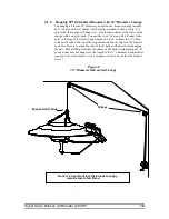
Figure 7 

34”or 48” Diameter Aluminum Canopy 

Note: It is important that the brooder canopy 

remains level at all times. 

Hanging Bracket Assembly 

Pulleys 


Summary of Contents for BJ-C-32-SPI

Page 1: ...ier Do not store or use gasoline or other flammable vapors and liquids in the vicinity of this or any other appliance 1 Ouvrez les fenetres 2 Ne touchez pas aux interrupteurs electriques 3 Eteignez to...

Page 2: ...NIT ASSEMBLY 5 5 4 BURNER UNIT ASSEMBLY 6 5 5 FINAL BROODER ASSEMBLY 6 5 6 GAS TUBING ASSEMBLY 8 6 INSTALLATION 9 6 1 HANGING THE UNIT 9 6 1 1 Hanging SPI Aluminum Brooder with 34 or 48 Diameter Canop...

Page 3: ...n with maximum load on supply and while brooder is in operation Burner manifold gas pressure is to be 7 0 in W C 17 4 mbar at maximum input rating Gas pressure should be checked by a certified gas tec...

Page 4: ...storage 7 Do not move or handle brooder while hot or burning 8 Turn off gas supply before servicing Brooder may start at any time 9 Brooder surfaces may be hot Do not permit feathers hay straw dust or...

Page 5: ...ed warranty of merchantability or fitness for a particular purpose The remedy set forth in this limited warranty shall be the exclusive remedy available to any person No person has authority to bind t...

Page 6: ...alve and is adjustable from 1 Low to 9 High 5 Assembly 5 1 Tools Required Wire pliers 1 2 wrench 7 16 wrench 11 32 nut driver Phillips screwdriver Gas leak testing solution Pipe thread sealing compoun...

Page 7: ...it is positioned with the mounting pedestals pointing inwards toward the center of the support ring as in Figure 3 5 3 Burner Unit Assembly 1 For burner unit assembly see Figure 3 then follow these st...

Page 8: ...final brooder assembly see Figures 5 and 6 Then follow these steps 2 Attach gas valve bracket to gas valve with three 10 24 X 1 4 screws Make sure the capillary tubing is not pinched by the gas valve...

Page 9: ...nd gas valve Cotter Pin Heat shield Canopy Thermocouple Ceramic Element Pilot Tube Gas Tube Burner Unit Assembly Capillary Tubing Gas Valve Gas Valve Bracket 10 24 X 1 4 Screws 8 32 X 1 4 Screws 8 32...

Page 10: ...into lower portion of the burner Use caution to keep the orifice bracket from becoming misaligned while tightening the orifice Misalignment will cause poor operation 3 Remove brass nut and ferrule fro...

Page 11: ...for the 34 48 diameter brooder canopy includes a 11 14 chain and two 6 chains which must be attached as shown in Fig 7 to ensure that the canopy will hang level Join the three chains in the center wi...

Page 12: ...s in the tops of the left and right suspension rods Connect the 11 chain with an S hook to the top of the suspension rod directly opposite the controls enclosure Be sure to crimp the ends of the S hoo...

Page 13: ...re gauge Note To obtain an accurate manifold pressure reading the brooder must be cycled on and off several times to stabilize the pressure regulator diaphragm 5 The gas pressure must be measured with...

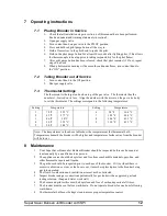
Page 14: ...the following temperatures Setting Temperature Setting Temperature 1 78 F 25 5 C 6 98 F 36 6 C 2 82 F 27 7 C 7 102 F 38 8 C 3 86 F 30 C 8 106 F 41 1 C 4 90 F 32 2 C 9 110 F 43 3 C 5 94 F 34 4 C Note T...

Page 15: ...o the ON position The burner venturi may be restricted Clean burner venturi to remove obstruction Pilot flame may not reach the burner Make sure the manifold gas pressure is set to manufacturer s reco...

Reviews: