Installation of Accessories
Installing in GBE Board
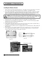
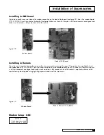
Open the controller cover and locate the modem connection on the back of the board (see figure 29). Insert line modem board
(P/N 01020307) into the socket on the back of the board. Make sure that all of the pins in all four connectors are aligned and
make sure the modem is fully seated into all of the sockets.
Installing in Remote
Open the remote monitor housing by removing the two screws and squeezing the sides of the monitor housing slightly. Insert
the modem board (P/N 01020307) into the socket on the back of the remote board (Figure 30). Make sure that all of the pins
in all four connectors are aligned and make sure the modem is fully seated into all of the sockets. Snap the two halves of the
remote housing back together using light finger pressure and insert the two screws.
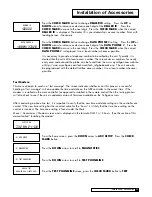
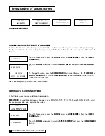
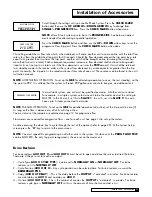
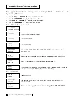
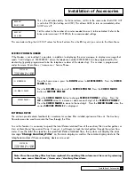
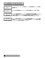
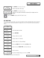
Modem Setup - GBE
system ok
7:32 am 2-1-08
Modem Board
Back of GBE Board
Figure 29
Modem Board
Back of Remote Circuit Board
Installation of Accessories
38
37
CULLIGAN GLOBAL ELECTRONIC CONTROLLER
Figure 30
Summary of Contents for GBE
Page 62: ...Menu Overview Continued on page 61 59 CULLIGAN GLOBAL ELECTRONIC CONTROLLER ...
Page 63: ...Menu Overview Menu Overview 60 ...
Page 64: ...Menu Overview Continued from page 59 61 CULLIGAN GLOBAL ELECTRONIC CONTROLLER ...
Page 65: ...Menu Overview Menu Overview 62 ...
Page 72: ...Appendix D 69 CULLIGAN GLOBAL ELECTRONIC CONTROLLER ...

