background image

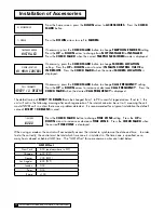
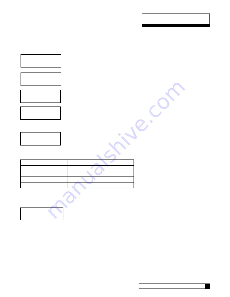
Manual cycling can be performed when the unit is starting either in SERVICE or while it is already within any 

portion of the REGENERATION process. If the unit is currently regenerating, the name of the current cycle position 

and the number of minutes remaining in the current cycle position will be displayed.

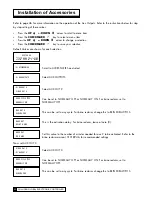
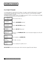
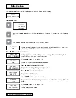
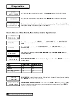
From the home screen, press the 

DOWN

 arrow to 

ADV. SETUP

.  Press the 

CHECK 

MARK

 button.

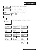
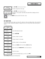
Press the 

DOWN

 button to scroll to 

DIAGNOSTICS

. Press the 

CHECK MARK

 button at 

DIAGNOSTICS

.

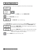
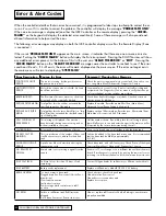
Press the 

DOWN

 button to scroll to 

MOTOR CONTROL

. Press the 

CHECK MARK

 but-

ton at 

MOTOR CONTROL

.

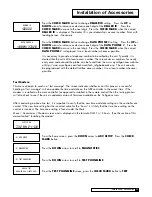
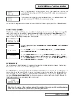
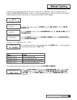
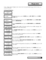
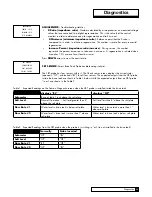
If control is not in regeneration, this is shown. 

To cycle the control valve without stopping press the 

CHECK

 button.  To stop the motor at 

the end of each cycle press the 

UP

 arrow.

Menu

Status

MOTOR AT POS S

Motor at service position

MOTOR AT POS B

Motor at backwash position

MOTOR AT POS E

Motor at brine draw/slow rinse position

MOTOR AT POS F

Motor at fast rinse/refill position

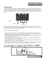
If cycling the control during regeneration, this screen is shown after 

MOTOR CONTROL

.

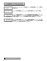
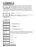
Press the 

CHECK MARK

 button to change 

REGENERATION

 setting.  Press the 

UP


or 

DOWN

 arrow to move to 

NEXT

 CYCLE, 

END REGEN NOW

 or

 END/CAN-

CEL TRIG

.   Press the 

CHECK MARK

 when the correct 

REGENERATION

 setting is 

displayed.

system ok

7:32 am 2-1-08

 > 5) adv setup

motor at pos s

up: forward

 > 5) diagnostics

 > 5) motor control

backwash minutes left: 8

>next cycle

Manual Cycling


Manual Cycling 

50

49

  CULLIGAN GLOBAL ELECTRONIC CONTROLLER

Summary of Contents for GBE

Page 1: ...GBE Softener Filter Controller For Commercial Industrial Applications Models from 2008 2008 Culligan International Com pa ny Cat No 01021161 Rev A 10 16 08 DCO 010703 Installation Operating and Service Instructions Printed in USA ...

Page 2: ... the party responsible for compliance could void the user s authority to operate the equipment WARNING Electrical shock hazard Unplug the unit before removing the cover or accessing any internal control parts WARNING This device complies with part 15 of the FCC rules subject to the two following conditions 1 This device may not cause harmful interference 2 this device must accept all interference ...

Page 3: ...erview 21 Commercial Setup 22 First Time Setup 23 27 Customizing the Setup 28 32 Progressive Flow 29 Regeneration 30 Cycle Times 31 Regeneration Triggers 32 Installation of Accessories 33 45 Aqua Sensor 33 Beeper Mode 33 Smart brine Tank Sensor 34 Wireless Remote 35 37 Modem 37 41 Low Meter 41 Progressive Flow 41 42 Brine Reclaim 42 43 Service Phone Number 44 Auxiliary Boards 46 48 Manual Regenera...

Page 4: ...p when keys are depressed to help identify valid short beep or invalid 3 short beeps pushes Can be enabled or disabled Power Source Electrical power required is 24 Volt 50 60 Hz AC current A UL listed plug in transformer 120V 24V is provided Time of Day Displays current time of day in either 12 hour or 24 hour format Real Time Clock with a 5 Year Battery Back up Keeps accurate time even during a p...

Page 5: ...e K factor to initiate a regeneration sequence AquaSensor Input Supports the patented digital Culligan AquaSensor technology used to efficiently initiate and control a regeneration sequence Telephone Modem o Calls in reports on regenerations and alarm conditions o Automatically updates time and date when calling in o Automatically checks for and installs and firmware updates when calling in Wirele...

Page 6: ...h up to six and as few as two mineral tanks in a system It allows more than one tank in a system to either be on line or off line depending upon the downstream flow demand If flow demand is greater than the flow capability of the tank on line another tank can be brought on line to help satisfy the excess demand Once the demand has decreased the second tank is returned to a standby mode and the sys...

Page 7: ...trical protection 4 DO NOT include the GBE wiring cables in any conduit or raceway containing other 120 volt or higher circuits 5 Maintain a distance of at least 10 feet between the GBE controller and any electrical distribution panels raceways carrying 300 volts or more and electrical motors of 1 horsepower or more 6 Use the cabling provided Failure to do so may effect performance of the GBE cont...

Page 8: ...or 4 on each controller provided 2 Using a small screwdriver loosen all the terminal strip binding screws on the main circuit board that do not contain wires by turning counterclockwise until the wire clamp has been fully opened see Figure 5 Installation Figure 3 Figure 5 5 CULLIGAN GLOBAL ELECTRONIC CONTROLLER Figure 4 ...

Page 9: ...ntroller enclosure for interconnecting wiring Install the plastic fittings as needed Remove the com pression nut and rubber sleeve from each fitting Prior to connection of the cable wires to the circuit board slide the compression nut and sleeve over the cable for the wiring connections When wiring is completed apply a small amount of silicone to the rubber sleeve and reassemble This will assure a...

Page 10: ...Multiple unit jumper Communication cable optional Flow meter cable optional Smart Brine Tank cable optional External regeneration signal connection optional Motor connection Programmable outputs optional Blocking valve connection optional Power cable from transformer Aqua Sensor cable optional Future use Do not connect anything to these Data port Figure 9 7 CULLIGAN GLOBAL ELECTRONIC CONTROLLER ...

Page 11: ... the other 2 Locate the cord grip among the parts 3 To assemble the power cord first run the cord grip nut over the spade terminal end of the power cord 4 Next run the spade terminals through a hole in the side of the controller FROM THE INSIDE See figure 10 5 Finally run the cable through the bottom end of the cord grip and assemble the grip to the controller wall 6 Plug the board connector to th...

Page 12: ...ire should be connected to one of the 24V terminals on the GBE control circuit board Figure 11 by way of the white connector 2 Repeat the process for the other 24V power supply wire attaching the second wire to the opposite terminal on the transformer and next to the other wire connected to the 24V pins on the GBE board Schematic Figure 11 POWER SUPPLY ONE transformer is required for each Control ...

Page 13: ...e Locate the cord grip fitting and nut Assemble them through the open hole and thread the solenoid coil cord through the cord grip fitting as shown in Figure 14 Tighten the cord grip onto the cord 3 Wiring Wire the valve to Aux Out 2 as shown in the diagram in Figure 15 The wires can be trimmed to a suitable length Solenoid Coil Screw Plastic Spacer 2 5VAC P9 Power 24VAC Vlv Aux1 Sol P7 Aux2 P8 P5...

Page 14: ...7 1 01016333 2 Triplex Progressive 01016327 2 01016334 3 Multiple units can be set up as progressive flow alternating or parallel operation Refer to the instructions and schematics below and on the following pages for connection to the circuit board Most multiple tank configurations will also require blocking valves with the exception of the Hi Flo 3e softener These are used to hold tanks offline ...

Page 15: ...ressive Parallel Communication Cable 01016327 Schematic 12 Schematic To RS 485 Comm Port on GBE Circuit Board 1 CABLE 01016327 To RS 485 Comm Port on GBE Circuit Board 2 PARALLEL Additional communication cable connections are used when there are 3 or more controls Connect end of 2nd 01016327 cable to this connector and other end of cable to RS 485 Comm Port on 3rd GBE Circuit Board To Additional U...

Page 16: ...ector from meter To Flow Meter Connection on GBE Circuit Board To RS 485Comm Port on GBE Ciruit Board 2 DUPLEX ALTERNATING Duplex Alternating with Meter option For triplex quad etc alternating you must use a meter on each unit and connect the same way as progressive flow Duplex Alternating Cable 01016342 Communication Cable 01016342 Figure 18 Unit 1 Unit 2 Flow meter ...

Page 17: ...ate infor mation totalization and volume based regeneration initiation There are several different types of flow measuring devices and differences in the wiring of the devices to the GBE circuit board do exist Refer to the drawings below For all but duplex alternating a meter needs to be connected to each circuit board at the location shown below in the drawing For duplex alternating meter connect...

Page 18: ...nsor It has two spade terminals on one end of the cable and two metal slip in tabs on the other 2 Locate the cord grip 3 The cable can be run through the cable grip and wall from either end of the cable Make sure the end with the metal tabs goes INSIDE the controller The spade terminals should be coming out the top end of the grip 4 Locate the connector at the end of the power cord You may have al...

Page 19: ...ally open normally no power to auxiliary output until power required or a normally closed contact user choice These 24VAC outputs can be used for energizing a relay coil only 2 1 Amp maximum power draw Refer to the section on Programming page 46 for additional information on the uses of this feature 3 4 Schematic 16 Schematic Figure 21 ...

Page 20: ...e can be as low as 0 seconds 6 seconds is the recommended minimum and default but can be as long as 999 seconds The contact must automatically open following the start of a regeneration sequence Connect this contact to the Aux In terminal shown in Figure 22 The illustration below is an example of how to use an external source to initiate regeneration NC NO 1 POLE NC NO 2 POLE C C SOL Regen Signal ...

Page 21: ...nning of the day Subtract this reserve capacity from the total capacity to determine capacity to signal Note If the reserve capacity is more than 1 3 of the total capacity a meter system may not reduce salt consumption relative to a timeclock system Multiple Tank Systems Multiple tank systems offer the benefit of continuous soft water supply When using the Aqua Sensor to initiate a regeneration se...

Page 22: ...beeper is available to assist the user by providing an audible tone about 70 decibels to signify valid 0ne beep and invalid three beeps key presses The beeper can be deac tivated in the programming mode If error occurs beep will still be ON even if set to No programming Programming Mode Timeout If there is no keypad activity for a 3 minute period while in the programming mode the controller will e...

Page 23: ...re you are in the menu The up and down arrows move thru the menu Pressing the checkmark key selects that item on the menu Here we see the current value for regeneration is OFF Press the check mark turns on the pointer symbol The pointer indicates that you can change the current value using the arrow keys The arrow keys allow you to scroll thru the available options Pressing the check mark key to s...

Page 24: ... item to set up any installed accessories This includes meters Aqua Sensor Smart Brine Tank probe Modem Wireless Remote Aux In and Aux Outs 5 ADVANCED SETUP This menu item allows customization of the unit There are 5 sub menus which offer customization settings 1 SYSTEM SETUP This menu allows customization of many of the initial setup information Water Hardness Iron Salt Type Resin Volume are amon...

Page 25: ...s is under Advanced Setup System Setup see pages 29 The MultiTank System setting is set to PROG FLOW for ALL multi tank systems Trip point settings will determine how unit operates progressive parallel or alternating page 42 4 If you are using immediate regeneration you must change the Reserve Capacity setting under Advanced Setup REGEN SETUP and the REGEN MODE See pages 30 5 Set Review Cycle Time...

Page 26: ...t he next question 2 Electronic Serial Number S N 00000123 This screen is very important as it shows the electronic ID number of the controller Note If this unit will be installed with a modem it is required that this electronic ID number is reported back to Culligan on the IQR form Press the DOWN arrow button to change the display to read Set Month 3 Set Month If the default selection is correct ...

Page 27: ...he DOWN arrow to accept that value and move to the next question 5 Set Year Set Year 2008 If the value displayed is NOT correct pressing the CHECK MARK button will change the display to show a symbol next to the displayed value Use the UP or DOWN arrow to change the setting Once the desired value is displayed this value can be accepted by pressing the CHECK MARK button Press the DOWN arrow to acce...

Page 28: ...tion 9 Set AM or PM Set am or pm 7 32 am If the value displayed is NOT correct pressing the CHECK MARK button will change the display to show a symbol next to the displayed value Use the UP or DOWN arrow to change the setting Once the desired value is displayed this value can be accepted by pressing the CHECK MARK button Press the DOWN arrow to accept that value and move to the next question 10 Se...

Page 29: ... the DOWN arrow to accept that value and move to the next question 13 Set Water Hardness water hardness 10 grains If the value displayed is NOT correct pressing the CHECK MARK button will change the display to show a symbol next to the displayed value Use the UP or DOWN arrow to change the setting Once the desired value is displayed this value can be accepted by pressing the CHECK MARK button Pres...

Page 30: ...n automatically homes Contact your Culligan Man if the settings need to be customized First Time Setup Process 27 CULLIGAN GLOBAL ELECTRONIC CONTROLLER Note For all commercial applications you must adjust the cycle times Most important is refill time Refer to the Brine System charts in the product s installation manual for cycle settings ...

Page 31: ...he Main Menu Advanced System Setup Menu 2 these items are changed on the Main Menu Advanced Regen Setup Menu 3 these items are changed on the Main Menu Advanced Regen Trigger Menu There may be times when the installer would prefer to override the default regeneration selections See Advanced Setup Menu Regeneration Setup Menu or Regeneration Trigger Menu for information on changing default selectio...

Page 32: ...i tank system Please refer to page 41 for details on setting up a multi tank system THIS CAN BE IGNORED FOR COMMERCIAL APPLICATIONS Enter the volume of resin in the tank This information can be found in the product s installation manual on the specifications page Enter in the units shown For US INCH enter the value in cubic feet Select either US INCH or METRIC units This will change the units when...

Page 33: ...n the manual shows the dosage at 102 pounds This setting is generally used for a single delay system For a multi tank system reserve capacity is not necessary and should be set to zero 0 If you do not change this value in a multi tank system your unit will regenerate when 30 of the capacity remains This setting is used for time clock regeneration This is the time of day that the unit will regenera...

Page 34: ...insed out properly within this time This value is calculated for household units For commercial units you should adjust this value to 10 minutes but it is not required This will only show if you have selected a 5 cycle valve This is the refill time This value can be found in the unit s installation manual For example if you have a Hi Flo 22 WS 90 water softener 3 ft and you want to set a capacity ...

Page 35: ...ing if using time clock regeneration only or if you would like to have a time clock backup for the installed trigger device It is common to set this at 3 days although not necessary The Predict Mode is used in the flow meter mode to determine the optimum regeneration point Before the regeneration starts the control will compare the remaining capacity value with the average daily water use If the a...

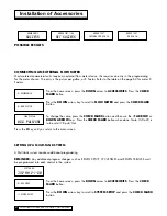
Page 36: ... SENSOR Press the CHECK MARK button to change AQUA SENSOR setting Press the UP or DOWN arrow to change from NOT INSTALLED to INSTALLED Press the CHECK MARK when the correct AQUA SENSOR mode is displayed Beeper Mode From the home screen press the DOWN arrow to ACCESSORIES Press the CHECK MARK button Press the DOWN arrow button to scroll to Beeper Press the CHECK MARK button at Beeper Press the CHEC...

Page 37: ...ess the CHECK MARK when the correct BRINE TANK AREA is displayed Press the CHECK MARK button to change SALT GEOMETRY setting Press the UP or DOWN arrow to change from PELLET ROCK OR BRICK Press the CHECK MARK when the correct SALT GEOMETRY is displayed 4 accessories system ok 7 32 am 2 1 08 5 sbt sensor sbt sensor installed salt geometry pellet brine tank area 500 sq in Installing the Smart Brine ...

Page 38: ...e remote monitor Hang the remote monitor on the two screws Disconnect power to the softener Open the control and connect the RF board into the controller circuit board Make sure the RF board is fully seated into all of the sockets Figure 28 Reconnect power Install RF board into unit controller Line up pins in RF board and press firmly into black connectors Note orientation of RF board Figure 28 Fo...

Page 39: ... the CHECK MARK button From the SETUP screen press the CHECK MARK button at RF SETUP Press the CHECK MARK button to change CHANNEL setting Press the UP or DOWN arrow to change CHANNEL Press the CHECK MARK when the correct CHANNEL is displayed Continue to press X to return to Home Screen remote display installed rf frequency 915 mhz channel 1 NOTE The CHANNEL for the control valve must be the same ...

Page 40: ...her the back of the main controller or the back of the remote control board The functionality of the modem is the same in either installation with the important exception that automatic firmware updating is ONLY available on units which have the modem installed on the main controller Before installing the modem into the back of the GBE board or the back of the remote the GBE circuit board or the r...

Page 41: ...monitor housing by removing the two screws and squeezing the sides of the monitor housing slightly Insert the modem board P N 01020307 into the socket on the back of the remote board Figure 30 Make sure that all of the pins in all four connectors are aligned and make sure the modem is fully seated into all of the sockets Snap the two halves of the remote housing back together using light finger pr...

Page 42: ...ll call in the following morning after each regeneration The interval can also be set to 0 meaning the unit would NEVER call in unless there was a problem detected It is recommended for a typical installation the default value of Every 10 regens is used Press the Check mark button to change Time zone setting Press the Up or Down arrow to increase or decrease Time zone Press the Check mark when the...

Page 43: ...his menu attempts to send in a test message The screen indicates whether or not this process is successful Sending a test message will also update the time and date on the GBE controller to the correct time If the modem is installed on the main controller as opposed to installed in the remote control then this testing process will also check to see if there is an updated version of firmware availa...

Page 44: ... when done Note Hi Flo 22 is to be set at 78 puls Gal Press the X key until you return to the main screen Setting up a Multi Tank System A Multi tank system requires additional programming REMINDER Any additional program changes such as REGEN SETUP CYCLE TIMES and REGEN TRIGGER must be programmed into each control in the system From the home screen press the DOWN arrow to ACCESSORIES Press the CHE...

Page 45: ... unit must be specified as master All other units are slaves For example in a triplex system select one unit to be the master and set this setting to MASTER In the 2nd unit set this to SLAVE 1 In unit 3 set it to SLAVE 2 You can have up to 5 slaves connected to a master NOTE PARALLEL OPERATION To set up the GBE for parallel operation all online set the trip point to zero 0 As long as the flow is a...

Page 46: ... OFF This can be set to any cycle For brine reclaim change this to BRINEDRAW POS This is the activation delay For brine reclaim leave at zero 0 Set this value to the number of minutes needed for aux 2 to be activated Refer to the brine reclaim manual 01018946 for recommended settings Now set AUX OUT 3 Select AUX OUT 3 Can be set to NORMALLY OFF or NORMALLY ON For brine reclaim set to NORMALLY OFF ...

Page 47: ...ark button to change Service phone setting Press the Up or Down arrow to increase or decrease each digit of the Service phone Press the Check mark to move to the next digit Press the Check mark when the correct Service phone is displayed External Filter The unit can provide alarm feedback for a sediment or carbon filter installed upstream of the unit The Auxiliary flow alarm can be used to monitor...

Page 48: ...Up or Down arrow to change from Installed to Not installed Press the Check mark when the correct External filter alarm mode is displayed Press the Check mark button to change FILTER CAPACITY setting Press the Up or Down arrow to increase or decrease FILTER CAPACITY Press the Check mark when the correct FILTER CAPACITY is displayed 11 ext filter external filter alarm installed filter capacity 10000...

Page 49: ...it reaches the chosen cycle position REPEAT CYCLE allows the output to turn on and off at a set interval during the cycle chosen Cycle Position AUX OUT X Any cycle position can be selected here This is the cycle position that the AUX OUT is activated turned on or off Delay AUXX OUT DELAY This is the delay before activating You can have the AUX OUT activation delayed a specified number of minutes i...

Page 50: ... minutes of AUX2 to 17 Here is how to set this up Scroll to ACCESSORIES and select Scroll to AUX OUTPUTS and select Scroll to AUX OUT 2 and select Leave this set at NORMALLY OFF We want the output to energize turn on the refill solenoid This should be set to SERVICE POS No delay is necessary For our example this would be set to 17 AUX OUTPUT 3 has the same menu options Refer to the chart on page 4...

Page 51: ...utes aux2 out off o Minutes aux 2 cycle type rep eat cycle aux out 2 service aux2 out gallons 0 aux2 out on 0 minutes normally on Type repeat cycle Type 1 2 4 Accessories system ok 7 32 am 2 1 08 To use the auxiliary contacts some configuration settings must be changed From the home screen press the DOWN arrow to ACCESSORIES Press the CHECK MARK button Press the DOWN arrow key to scroll to AUX IN ...

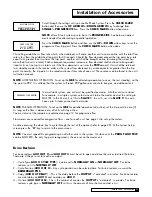
Page 52: ...he desired value is displayed this value can be accepted by pressing the CHECK MARK button By selecting the REGEN TONITE value the softener will regenerate that night at 2 00 AM or at the preset regeneration time By selecting the REGEN NOW value the softener will begin regeneration immediately NOTE In multi tank systems the regeration request is sent to the master control and it will allow the uni...

Page 53: ...ion this is shown To cycle the control valve without stopping press the CHECK button To stop the motor at the end of each cycle press the UP arrow Menu Status MOTOR AT POS S Motor at service position MOTOR AT POS B Motor at backwash position MOTOR AT POS E Motor at brine draw slow rinse position MOTOR AT POS F Motor at fast rinse refill position If cycling the control during regeneration this scre...

Page 54: ...a Smart Brine Tank Sensor is installed Press DOWN arrow to view next screen Displays the percent softening capacity remaining Press DOWN arrow to view next screen Displays the remaining softening capacity in gallons Press DOWN arrow to view next screen Displays the current flow rate Press DOWN arrow to view next screen Displays the date when the next regeneration will occur based on average daily ...

Page 55: ...the correct time each time it calls in To set the date and time Scroll to Information and select Scroll to SET TIME Scroll up or down to set month Scroll up or down to set the date Scroll up or down to set the year 4 digit Choices are 24 HR 00 00 to 23 59 or 12 HR AM PM Based on choice of CLOCK TYPE scroll to select the hour Scroll to set minutes If you observe daylight savings in your area set to...

Page 56: ...ife at Main Menu Advanced Setup Regen Settings Media Life Replace Aux Filter Media Total gallons thru the secondary filter i e Big Blue filter has exceeded the specified capac ity of the big blue Replace optional filter cartridge Reset the aux Filter media life at Main Menu Accessories Aux Filter menu Call Culligan at xxx xxx xxxx This message is displayed if an error has been detected that requir...

Page 57: ...iew the next statistic This is the number of REGENS IN LAST 14 DAYS of operation Press DOWN arrow to view the next statistic This is the number of DAYS SINCE LAST REGENERATION of unit Press DOWN arrow to view the next statistic This is the date of last regeneration of unit January 3 Press DOWN arrow to view the next statistic This shows what device triggered the last regeneration Press DOWN arrow ...

Page 58: ...nsors MAIN BOARD POSITION Position of Home Program switches Press DOWN arrow to view the next statistic Cycle Home Switch Program Switch Service Off Off Backwash On On Brine Draw Slow Rinse On Off Fast rinse Refill On On FLOW METER Current pulses per second K Factor refer to page 63 to varify correct reading Press DOWN arrow to view the next statistic AQUASENSOR SUPPLY VOLTAGE This will be either ...

Page 59: ...ked BL for all four sensors The expected outputs from the SBT probe inside the brine tank are shown in Table 1 below while the expected outputs from an SBT probe in air are shown in the Table 2 Table 1 Expected Readings on the Sensor Diagnostic screen when the SBT probe is installed inside the brine tank displays BL displays OP Salometer Brine at least 1 inch above the salt plate Salt Level Normal...

Page 60: ... LAST T3 Smart Brine Tank Probe troubleshooting statistics This is the last T3 valve recorded by the probe Press DOWN arrow to view the next statistic Test Wireless See page 37 Test Progressive Flow Scroll to Advanced setup and select Scroll to Diagnostics and select Scroll to Test Progressive Flow and Select The progressive test screen will show the data packet transmissions from the Master Tx an...

Page 61: ... Menu Default Below is the procedure to default the board to factory settings and begin the FIRST TIME SETUP 1 Power down the control 2 Press and hold UP and CANCEL buttons 3 Power up the control while continuing to hold UP and CANCEL buttons for at least 5 seconds 4 Release UP and CANCEL buttons display should be blank if not go back to step 1 5 Power down the control 6 Power up the control again...

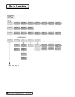
Page 62: ...Menu Overview Continued on page 61 59 CULLIGAN GLOBAL ELECTRONIC CONTROLLER ...
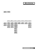
Page 63: ...Menu Overview Menu Overview 60 ...

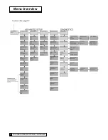
Page 64: ...Menu Overview Continued from page 59 61 CULLIGAN GLOBAL ELECTRONIC CONTROLLER ...
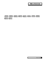
Page 65: ...Menu Overview Menu Overview 62 ...

Page 66: ... 1 6 106 117 9 446 3 2 2 7 179 66 7 252 5 2 5 3 8 256 43 0 162 8 3 6 0 401 26 7 102 1 Sch 40 Galvanized Tee 1 0 7 44 213 0 806 2 1 25 1 2 80 127 7 483 3 1 5 1 7 110 94 4 357 3 2 2 8 184 58 4 221 Type K Copper Tee 1 0 7 48 256 4 970 5 1 25 1 1 75 176 4 667 7 1 5 1 6 107 115 7 437 9 2 2 8 187 63 4 240 Type L Copper Tee 1 0 8 51 241 6 914 5 1 25 1 2 78 170 9 646 9 1 5 1 7 110 112 0 423 9 2 2 9 192 61...

Page 67: ...ard 01020497 Replacement Key pad 01020748 Auxiliary Board 01020747 Modem Board 01020750 RF Board 01020553 Remote Display Complete 0101 Transformer 01020447 Smart Brine Tank Accessory 01008779 Aqua Sensor Steel Tank 01018959 Aqua Sensor Fiberglass Tank CR 2032 Battery Cables and Kits 01016327 Communication Cable 01016342 Communication Cable Duplex Alternating 01016333 Duplex Progressive Kit 0101633...

Page 68: ...type of equipment is being controlled by the GBE Single Water Softener or Filter controlled by GBE The format of the status message is CULL A B C D E F Example CULL 52754 57 2 1 911 0x0000 1 Where the values for the fields A thru F are as follows A total gallons since new B current flow rate in gallons per minute 57 2 means 57 2 gallons per minute C Current Status Indicator 0 initialization 1 serv...

Page 69: ...e GBE is controlling a Filter instead of a water softener then the above message definitions are identi cal but that error flags 1 2 3 6 9 and 11 will always be zero for a filter Progressive Flow System of Water Softeners controlled by GBE The format of the status message for a progressive flow network consists of a series of individual lines of informa tion one line for each of the gbe controlled...

Page 70: ...CD ROM which includes device drivers for Microsoft Windows VISTA XP and Windows 2000 operating systems Test Data Port Once your cables are set up you can test your connection using the Windows Hyperterminal program This program is generally found under Start All Programs Accessories Communications Hyperterminal When you open Hyperterminal it will ask you to create a name for the connection Enter a...

Page 71: ... the screen that will look similar to this CULL 52754 57 2 1 911 0x0000 1 This message was described at the beginning of this Appendix MINI REPORT SN 00001078 Date 9 4 8 Time 14 02 Total 28696 GAL regen 14d 0 trigger Power Outage type softener hardness units US Hardness 25 grains Resin 1 00 cu ft avg mon 710 GAL avg tue 937 GAL avg wed 1201 GAL avg thr 839 GAL avg fri 1364 GAL avg sat 85 GAL avg s...

Page 72: ...Appendix D 69 CULLIGAN GLOBAL ELECTRONIC CONTROLLER ...
Page 73: ...63 Manual Cycling 50 Manual Regeneration 49 Menu Lockout 58 Metric 30 Modem 2 21 22 23 35 37 41 53 64 Multi Tank Systems 42 Outputs 2 11 16 43 46 48 Parallel 11 12 22 42 Parts List 64 Phone Number 40 44 PLC Output 65 Programming 18 58 Progressive Flow 2 3 11 12 13 21 22 29 41 42 64 Pulses per gallon 41 Quick Reference 70 Reclaim 2 22 43 Refill 6 10 22 27 31 47 48 50 55 Regeneration 30 31 Remote 2 ...

Page 74: ...This page contains materials and DCO in for ma tion IT DOES NOT PRINT AS PART OF THE DOC U MENT VENDOR MUST SUBMIT A MATERIAL CERTIFICATE OF COMPLIANCE WITH EACH SHIPMENT LET CHANGE BY APRVD DCO DATE A NEW ART CREATED BSM KR 010703 08 13 08 A1 Revisions BSM KR 010703 09 04 08 A2 Revisions BSM KR 010703 09 18 08 A3 Revisions BSM KR 010703 09 25 08 A4 Minor revisions BSM KR 010703 10 02 08 A5 Minor ...

Reviews: