background image

Aerial work platform 

ZED 20.3 HV

11

COD. UM0284_GB | REV. 0.0 | ED: 09/17

Chapter 8

GB

MAINTENANCE

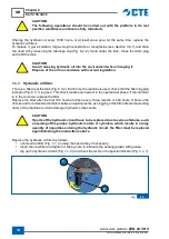
CAUTiOn
Be careful not to release hydraulic oil into the environment when changing it. 

Dispose of the ilter in accordance with the law.

8.6.7 

Restore levelling of work platform

CAUTiOn
if you notice that the work platform is not level with respect to the horizontal, 
lower it to the ground and get off.

This maintenance work must be performed by a qualiied technician (M).

DAnGEr
THE presence of personnel inside the working platform during these operations 
is strictly prohibited.

Restore safe working conditions (work platform in horizontal position), as follows:

1) 

Remove the key fastened to the structure by the lead wire seal.

2) 

access the “emergency ground controls” settings (Fig. 4.4);

3) 

Place the key in the selector switch (Fig. 4.4, 6), rotating to the right to the “Emergency Control” 
position;

4) 

activate the extensible boom lifting selector (Fig. 4.4, 14). Keep the selector switch pressed 
and at the same time use the joystick (Fig. 4.4, 10), until the work platform about a half metre;

5) 

activate the boom extension selector (Fig. 4.4, 13). Keep the selector switch pressed and at the 
same time use the joystick (Fig. 4.4, 10), until the work platform is raised about a half metre;

6) 

carefully get up on the bed and open the diverter block lock (Fig. 8.4 4) with the key provided 
by the Safety Manager, raising the silver coloured lever (Fig. 8.4, 5) on the turret;

7) 

turn both of the two-position diverter valves (Fig. 8.4, 6 & 7) by two positions;

8) 

get down from the bed of the vehicle and press the “extend telescopic boom” selector (Fig. 
4.4, 13) and, without letting it go, press the joystick which controls movement speed (Fig. 4.4, 
10). By doing this it is possible to level the working platform (completely lower and raise the 
platform and then align it).

9) 

After completing these operations, place both of the two-position deviator valves, located at the 
base of the extension boom, back into their original position (extension position, indicated by 
the label 

A

. Remove the lever from the deviator valves, put it back it in the turret and secure it 

using the black locking knob).

10) 

attach the padlock in the locking position, close it and give the key back to the safety manager.

11) 

check that the extension boom works correctly by pressing the switch that controls the extension 
of the boom and using the potentiometer lever. Retract the extension boom into its rest position.

12) 

Place the key selector switch (Fig. 4.4, 6) in the “ baskt controls” position;

13) 

Remove the key and close the cover of the control panel.

Summary of Contents for ZED 20.3 HV

Page 1: ...COD UM0284_GB REV 00 ED 09 17 FABRICATION NR INSTRUCTIONS FOR USE AND MAINTENANCE MOBILE ELEVATING WORK PLATFORM 20 3 HV...

Page 2: ...produce store or alteration even partial of this publication without written permission by the CTE SPA CTE S P A reserves the right to make changes to the lifting platform for any technical and commer...

Page 3: ...___________________________ 3 2 3 1 Electrocution hazard 3 2 3 2 Tipping hazard 4 2 3 2 1 BEAUFORT wind scale 5 2 3 3 Risk of falling 6 2 3 4 Collision hazard 7 2 3 5 Work atmosphere hazards 7 2 3 6 M...

Page 4: ...____________________ 2 4 3 Ground control panel _____________________________________________________ 3 4 4 Cabin control panel_______________________________________________________ 6 4 5 Emergency c...

Page 5: ..._ 2 7 4 Lowering the work platform using the ground controls in the event of operator incapacity 3 7 5 Lowering the work platform in the event of a power cut ___________________________ 4 7 6 Manual l...

Page 6: ...nto a vehicle__________________________________________ 1 10 2 Storage________________________________________________________________ 2 11 Support and Warranty 1 11 1 After Sales services and spare p...

Page 7: ...platform ZED 20 3 HV 7 COD UM0284_GB REV 00 ED 09 17 15 2 5000V Insulated work platform______________________________________________ 1 15 3 Auxiliary electric motor __________________________________...

Page 8: ...8 Hubarbeitsb hne ZED 20 3 HV COD UM0283_DE REV 00 ED 09 17 GB INDEX This page intentionally left blank...

Page 9: ...orming maintenance operations that do not comply with the instructions in this manual shall relieve the Manufacturer of any responsibility for damage or injury The customer shall bear responsibility f...

Page 10: ...1 Symbols For the purposes of personal and material safety in preparing this document particular symbols have been used to draw attention to dangerous conditions warnings and other relevant informatio...

Page 11: ...descriptions assume that the machine will only be used by operators trained speciically to operate this type of machine This manual cannot in any way substitute adequate operator training The operator...

Page 12: ...tions for use intended for the personnel in charge of operating the lifting platform 7 MANOVRE D EMERGENZA speciies the main emergency operations to perform if necessary 8 MAINTENANCE contains the mai...

Page 13: ...cab dashboard so it can be readily consulted at any moment The manual must always accompany the machine along with the CE declaration of conformity the check register and any other documents relating...

Page 14: ...al connection for at least a part of the distance between the control console and the rest of the control system Transport position Configuration of the mobile aerial work platform established by the...

Page 15: ...obabilities and the degree of seriousness of the possible injuries or possible health damages in a dangerous situation rotation Circular movement of the work platform around the vertical axis Extensio...

Page 16: ...consists of a telescopic or articulated boom or a combination thereof and may or may not slew on its base Chassis Base of the mobile elevating work platform It means the carriage in the case of self p...

Page 17: ...30 EU OF THE EUROPEAN PARLIAMENT AND COUNCIL dated 26 February 2014 on the harmonisation of the laws of the Member States relating to electromagnetic compatibility recast 2014 35 EU 26 02 2014 DIRECTI...

Page 18: ...s for systems and their components iEC En 60204 1 2006 2006 Safety of machinery Electrical equipment of machines Part 1 General requirements Uni En iSO 13850 2008 November 2008 Safety of machinery Eme...

Page 19: ...plosive materials etc because of their chemical physical characteristics load the platform when it is raised 2 3 Obligations and requirements DAnGEr failure to comply with safety standards could cause...

Page 20: ...ductors due to wind Failure to comply with the minimum safety distances can cause death or serious injury 2 3 2 Tipping hazard Before using the machine make sure that the ground is able to support the...

Page 21: ...orm as a crane applying loads outside the platform and using the machine to raise suspended loads Use the machine as a goods lift raising loads on the platform Use the machine as a passenger lift movi...

Page 22: ...in to sway crested wavelets form on inland waters Moderate waves taking a more pronounced long form many white horses are formed chance of some spray 6 Strong breeze 22 27 39 49 Large branches in moti...

Page 23: ...when operating the machine Lower the boom only if the area below is completely free from personnel and or obstructions 2 3 5 Work atmosphere hazards iT iS OBliGATOrY TO always use the machine in a su...

Page 24: ...chine that is damaged or faulty Never use the machine if there is leakage of hydraulic oil or air Leakage of hydraulic luid or air could cause skin damage and burns Ensure that all maintenance checks...

Page 25: ...rators aged 18 and over It is forbidden for the lifting platform to be used by subordinate workers employed as apprentices THE employer must ensure that The operator fulils all vocational requirements...

Page 26: ...ng platform commissioning procedure engagement of the power take off positioning of the stabilisers etc Assessment of the solidity and latness of the ground on which the platform will be stabilised Pr...

Page 27: ...he use and maintenance instructions provided by the manufacturer Operators must comply with the current accident prevention regulations when working on the platform Do not use the platform if it is ma...

Page 28: ...6 1 Type of workplace The machine was designed and built for use in the following types of locations Open air places accessible to the public e g squares car parks public roads etc Private open air p...

Page 29: ...to be carried out successfully whilst maintaining safety within the working envelope During this phase the accessibility of the controls and the visibility of the applicable areas should be checked w...

Page 30: ...nd under the following working conditions 2 6 5 Ambient air temperature The electrical equipment is designed to operate correctly at air temperatures between 10 C and 40 C 2 6 6 Humidity The electrica...

Page 31: ...for use 2 6 11 Ionising and non ionising radiation The electrical equipment DOES nOT have additional protection against radiation microwaves ultra violet rays laser X rays If the machine is likely to...

Page 32: ...restraint or positioning adjustable lanyard EN 354 EN358 and 2 connectors EN 362 of a shape and size suitable for connection to the ends of the lanyard Note the pictures above are provided purely as...

Page 33: ...on to the harness system the use of the aerial work platform foresees the use of a safety helmet for overhead works with chinstrap EN 397 and footwear for professional use EN 346 Other equipment may b...

Page 34: ...This page intentionally left blank 18 Aerial work platform ZED 20 3 HV COD UM0284_GB REV 0 0 ED 09 17 GB Chapter 2 SAFETY...

Page 35: ...ntinuous rotation of the elevating work platform by limiting it to 320 It only it allows it to return to its starting point The boom unit ixed to the turret is composed of two articulated arms actuate...

Page 36: ...al and not intended by the manufacturer is forbidden The machine has been designed for an expected 100 000 work cycles and a heavy work regime e g 10 years 50 weeks a year 40 hours a week 5 cycles an...

Page 37: ...485099 PIATTAFORMA DI LAVORO MOBILE ELEVABILE MOBILE ELEVATING WORK PLATFORM MODELLO MODEL TIPO TYPE NUMERO DI FABBRICA FABRICATION NUMBER ANNO DI COSTRUZIONE YEAR OF CONSTRUCTION PORTATA MASSIMA kg R...

Page 38: ...evating work platform 4 Articulated boom 14 Control board on work platform 5 Turret 15 Boom 6 Ground electrical panel 16 Articulated lifting cylinder 7 Stabiliser control levers 17 Emergency controls...

Page 39: ...n DE lA PlATAfOrMA HET iS VErBODEn ZiCH BinnEn HET WErKBErEiK VAn DE MACHinE TE BEGEVEn iSO VG32 E vietato collegare utensili di tensione diversa dai 230V e potenza superiore ai 1 5 kW Prima di colleg...

Page 40: ...ltage 12 V Controls Proportional electro hydraulic Hydraulic oil reservoir capacity 15 l Hydraulic system oil ARNICA ISO VG 32 40 l Hydraulic system oil RENOLIN MR 520 40 l Grease for turret gearbox N...

Page 41: ...k booklet supplied and which is an integral part of the machine niSSAn 35t Dimensions in running order data refers to the vehicle illustrated Length in running order 6632 mm Width in running order 210...

Page 42: ...ICAL DATA 3 8 Working envelope 3 8 1 Plan view of work area The following illustration shows in a plan view the maximum capacity allowed in relation to the boom extension to the angular position of th...

Page 43: ...Aerial work platform ZED 20 3 HV 9 COD UM0284_GB REV 00 ED 09 17 Chapter 3 GB DESCRIPTION AND TECHNICAL DATA niSSAn 35t fBr BASKET Fig 3 7...

Page 44: ...10 Aerial work platform ZED 20 3 HV COD UM0284_GB REV 00 ED 09 17 GB Chapter 3 DESCRIPTION AND TECHNICAL DATA 3 8 2 Work envelopes and load according to the stabilisation niSSAn 35t Al BASKET Fig 3 8...

Page 45: ...Aerial work platform ZED 20 3 HV 11 COD UM0284_GB REV 00 ED 09 17 Chapter 3 GB DESCRIPTION AND TECHNICAL DATA niSSAn 35t fBr BASKET Fig 3 9...

Page 46: ...This page intentionally left blank 12 Aerial work platform ZED 20 3 HV COD UM0284_GB REV 00 ED 09 17 GB Chapter 3 DESCRIPTION AND TECHNICAL DATA...

Page 47: ...e who is unable to move on the platform When the ground control panel is active the controls on the platform are not operational 3 Control panel on work platform Main control station Standing operator...

Page 48: ...tracts the stabiliser 2 Back left stabiliser control lever 3 Front left stabiliser control lever 4 Front right stabiliser control lever 5 Front right outrigger control lever lowering the lever causes...

Page 49: ...um stabilisation has been accomplished 4 Back right stabiliser indicator light Switches on when the stabiliser is on the ground and minimum stabilisation has been accomplished 5 Emergency stop button...

Page 50: ...h to raise lower the articulated boom Keep the selector in the up position to raise the articulated boom Keep the selector in the down position to lower the articulated boom 3 Three position spring re...

Page 51: ...controls in the working platform Turn the key to the central position to disable the mobile control console 10 Three position spring return to centre selector switch controls the motor Keep the select...

Page 52: ...e power take off PTO is engaged 3 red stabilisers lowered indicator light When lit it indicates that the stabilisers have not been completely retracted 4 Green stabilisers retracted indicator light Wh...

Page 53: ...n the upper knob to extend the telescopic boom tighten the bottom knob to retract the telescopic boom 4 Solenoid valve to raise the telescopic boom tighten the upper knob to raise the telescopic boom...

Page 54: ...ee position spring return to centre proportional lever extends retracts the telescopic boom Keep the lever in the up position to extend the telescopic element Keep the lever in the down position to re...

Page 55: ...mergency stop button pressing the emergency stop button disables all the controls and the vehicle engine switches off 4 7 Power take off control The power take off control depends on the model of the...

Page 56: ...This page intentionally left blank 10 Aerial work platform ZED 20 3 HV COD UM0284_GB REV 0 0 ED 09 17 GB Chapter 4 CONTROLS...

Page 57: ...Fig 5 1 1 2 and 3 in order to stop the machine in the event of an emergency Pressing the emergency button causes the electrical functions of the machine to be interrupted immediate stop of all movemen...

Page 58: ...Fig 4 6 two are in the mobile ground control console Fig 4 4 Within the cab panel the irst is activated accompanied by a continuous sound when the PTO is activated the second is activated accompanied...

Page 59: ...4 Stabilisers interlock switch the device Fig 5 3 1 is formed by a sensor on the boom rest bracket and a receiver under the telescopic boom It only allows the stabilisation controls to be activated w...

Page 60: ...micro switches on the vehicle s rear springs which detect minimum stabilisation When the machine is being stabilised indicator lights 1 2 3 and 4 next to the stabilisation controls will light up only...

Page 61: ...into the hole on the pump and move it vigorously CAUTiOn The manual pump will function only after it has been completely illed with oil 2 3 1 Fig 5 4 SAfETY DEViCE fUnCTiOnAliTY CHECK Turn off the en...

Page 62: ...d and if there is a lack of pressure e g due to breakage of a delivery pipe they prevent the uncontrolled movement of the corresponding cylinder The on off blocking valves Fig 5 6 are located at the t...

Page 63: ...iTY CHECK When the stabilisers are properly extended the four LEDs 1 2 3 and 4 next to the stabilisation controls see Fig 4 3 light up indicating that the micro switches are working correctly Fig 5 7...

Page 64: ...panel lights up and the platform is entirely closed reach to be driven on the road 2 1 Fig 5 9 5 12 Working area control device The working control device consists of one micro switch Fig 5 9 1 found...

Page 65: ...rossways axis of the stabilisers if the spirit level on the machine is faulty contact technical assistance services 5 14 Anchorage points for the harness device The lifting platform comes with two anc...

Page 66: ...This page intentionally left blank 10 Aerial work platform ZED 20 3 HV COD UM0284_GB REV 0 0 ED 09 17 GB Chapter 5 SAFETY DEVICES...

Page 67: ...GEr failure to observe the following warnings could create dangerous situations and cause damage to property and or injury to persons iT iS OBliGATOrY TO Comply with national standards and legislation...

Page 68: ...when it is already raised from the transport position leave the platform unattended in a position other than the transport position without removing the keys from the control panel use the platform if...

Page 69: ...re present and legible see Section 3 5 check the level of hydraulic oil and top up if necessary see chapter 8 Maintenance inspect the aerial work platform checking the following components and areas f...

Page 70: ...ton 2 on the control panel that activates the PTO the PTO indicator 5 will come on an acoustic warning signal will sound and the hour counter will start if the vehicle has an electromagnetic clutch wi...

Page 71: ...xtend the stabilisers upwards to retract Fully extend the stabilisers to lift up the vehicle and take the weight off the suspension Check the spirit level Fig 6 3 7 located under the stabiliser contro...

Page 72: ...a safety harness and any other PPE that may be necessary before getting on the platform carefully get onto the work platform check that the access gate is closed connect the snap hook of the harness t...

Page 73: ...itch off the engine once you have reached the work position press the selector switch fig 6 4 8 downwards To restart press the selector switch fig 6 4 8 upwards CAUTiOn On the machines equipped with a...

Page 74: ...to the stabilisers position Fig 6 2 9 retract the stabilisers completely by operating the levers Fig 6 3 1 2 3 4 retract the beams completely by operating the levers Fig 6 3 5 check that the stabilis...

Page 75: ...tly to the Highway Code 6 4 Parking Park the machine in a suitable area out of the way of trafic The ground must be level and irm If parking on a slope or on an inclination apply the handbrake and cho...

Page 76: ...This page intentionally left blank 10 Aerial work platform ZED 20 3 HV COD UM0284_GB REV 0 0 ED 09 17 GB Chapter 6 PROCEDURES FOR USE...

Page 77: ...e the platform safely and immediately contact CTE authorised repair shop to have the normal machine use conditions restored CAUTiOn in some set ups the machine is provided with optional equipment such...

Page 78: ...e cause of the emergency has been resolved reactivate the controls by rotating the button by a quarter of a turn 1 2 3 Fig 7 1 CAUTiOn read and understand the previous chapters before reading this one...

Page 79: ...seal 2 insert the key in the selector switch 11 and turn it to the Mobile Console Control position 3 activate the control switch for the required movement and at the same time use the proportional jo...

Page 80: ...t re position the manual pump control lever ixing it on the ladder using the black locking knob 2 3 1 Fig 7 3 7 6 Manual lowering of platform from the ground If the vehicle s engine breaks down the ge...

Page 81: ...1B and the valve Fig 7 5 7 D Open the turret valve Fig 7 5 5A or 5B Set the required travel speed using the proportional valve Fig 7 5 7 After completing the manoeuvre close the valve Fig 7 5 5A or 5...

Page 82: ...This page intentionally left blank 6 Aerial work platform ZED 20 3 HV COD UM0284_GB REV 0 0 ED 09 17 GB Chapter 7 EMERGENCY MANOEUVRES...

Page 83: ...hould only be carried out by After Sales Services or by Service Centres authorised by the manufacturer The aerial platform can work in contact with water sand earth etc and requires regular lubricatio...

Page 84: ...nance of the inspection logbook The Inspection Logbook should be kept at the disposal of supervisory bodies for a period of ive years from the date of the last record or until the equipment is put out...

Page 85: ...he platform and on the ground O 8 7 1 Check safety devices Emergency Stop O 8 7 1 Test limit switches O 8 7 2 Test power supply differential circuit breaker in the platform O 15 3 O to be done by an o...

Page 86: ...ightness of all connecting bolts from the subframe to the truck M 8 8 2 O to be done by an operator M to be done by a qualiied technician 8 3 4 Every 6 months or 500 hours of operation Description of...

Page 87: ...Hydraulic oil level check O 8 6 5 Check hydraulic oil ilter clogging indicators O 8 6 6 Check the operation of the controls in the platform and on the ground O 8 7 1 Check safety devices Emergency Sto...

Page 88: ...rret the locks on the pins the ixing nuts on the vehicle all other bolts particularly on parts subjected to vibration and movement Before each use also visually inspect all the structural components f...

Page 89: ...To grease the articulated joints inject a small quantity of grease using a greasing pump Fig 8 1 C inject pressurised grease through the domed grease nipples until the old lubrication grease comes out...

Page 90: ...m Check the lubrication of the elements If they are dusty or dirty clean them and remove the grease Then using a brush apply a thin layer of Agip F1 GR MU2 grease mixed with 50 of Agip OSO32 hydraulic...

Page 91: ...ment Check the maximum pressure valve stabilise the platform properly retract the boom by pressing the relevant button on the ground control panel and check that the pressure on the manometer correspo...

Page 92: ...er clogging indicator Fig 8 3 1 is green This check must be carried out in the operational phase If the indicator is in the red area replace the ilter Replace the ilter after the irst 100 hours and th...

Page 93: ...joystick Fig 4 4 10 until the work platform is raised about a half metre 6 carefully get up on the bed and open the diverter block lock Fig 8 4 4 with the key provided by the Safety Manager raising th...

Page 94: ...check that the emergency stop buttons work properly CAUTiOn There should be nobody on the work platform during the test Go onto the work platform and repeat the test using the controls on the platfor...

Page 95: ...02 18 x 2 5 288 406 20 x 2 5 409 576 22 x 2 5 554 780 24 x 3 708 996 CAUTiOn reduce M by 10 when tightening is carried out using cordless tightening machines the screws are galvanised POSiTiOn Of PlAT...

Page 96: ...M 1 transport position 2 vehicle switched off SliDinG BlOCK WEAr CHECK The special adjustable blocks Fig 8 9 1 help reduce sliding friction when the boom is extended check the wear and tear of the pad...

Page 97: ...ceed as follows 1 Thoroughly clean the points on which the measurement to be taken 2 Lift the boom up until it is at 0 and extend it completely until it reaches its maximum extension with the turret a...

Page 98: ...or greasing the screw Fig 8 11 1 and those for greasing the slewing ring Fig 8 11 2 In order to grease the inside of the slewing ring you need to access the inside of the turret by removing the cover...

Page 99: ...ntrol panels and electrical equipment do not clean the machine of there is live electrical equipment wear suitable personal protective equipment only clean the machine in areas speciically set aside f...

Page 100: ...This page intentionally left blank 18 Aerial work platform ZED 20 3 HV COD UM0284_GB REV 0 0 ED 09 17 GB Chapter 8 MAINTENANCE...

Page 101: ...t safety footwear gloves goggles and mask that are compliant with the applicable safety standards Make sure that the machine is disconnected from all power sources Check that the hydraulic pneumatic a...

Page 102: ...terials steel aluminium rubber electric cables should be separated into different containers To dispose of polluting substances PVC lubricant oil and synthetic gum comply with the standards in force i...

Page 103: ...ng devices are effective and in good working order Ensure that the platform is fully retracted and locked into its rest position Check that the stabilisers have been fully retracted Read all loading o...

Page 104: ...t term long term Clean the machine Park the machine in a dry covered place Lock the doors Remove the keys from the vehicle and lifting platform MEWP to prevent unauthorised use If the machine is itted...

Page 105: ...vailable for carrying out any work that may be required Please contact After Sales Services for any information you may require CAUTiOn in order for the machine to operate correctly and to avoid damag...

Page 106: ...annot be held responsible for any expenses sustained by the commercial agent and customer any supposed present or future damage loss of earnings forfeits etc The warranty does not cover the replacemen...

Page 107: ...ents that do not move smoothly when irst moved Hydraulic oil temperature too low Carry out idle operation for a few minutes in order to heat up the oil Vibrations during all movements when oil is hot...

Page 108: ...seals Replace seals Emergency stop button pressed Rotate the button until it reaches normal position Solenoid valve blocked Dirt inside Use the solenoid valve cursor to try to unblock it and contact...

Page 109: ...mantle and clean the max pressure valve or replace it lights do not work Burnt out bulb Replace the bulb Broken electrical connection Repair the connection Burnt out fuse Replace the fuse Excessive he...

Page 110: ...rM 0x 01 01 spieAlarm_MMSSafetyNoCan 02 spieAlarm_MMSTorr1NoCan 03 spieAlarm_MMSTorr2NoCan 04 spieAlarm_MMSCestelloNoCan 05 spieAlarm_MMSPulsCarroNoCan 06 spieAlarm_MMSSafetyNoGND 07 spieAlarm_MMSTorr...

Page 111: ...eAlarm_pressPistoneTorr2VBat 09 spieAlarm_pressSteloTorr2Open 0x 05 01 spieAlarm_pressSteloTorr2VBat 02 spieAlarm_pressSiloTorr2Open 03 spieAlarm_pressSiloTorr2VBat Alarm code Description AlArM1 AlArM...

Page 112: ...panel 1 which is found on the bed of the vehicle open the cover panel to the compartment 2 then open the panel 3 covering the box which contains the Safety and Carriage engine control units the error...

Page 113: ...Chapter 13 GB DIAGRAMS AND ATTACHMENTS Aerial work platform ZED 20 3 HV 1 COD UM0284_GB REV 0 0 ED 09 17 13 Diagrams and Attachments 13 DiaGraMs anD attachMents...

Page 114: ...GB Chapter 13 DIAGRAMS AND ATTACHMENTS 2 Aerial work platform ZED 20 3 HV COD UM0284_GB REV 0 0 ED 09 17 13 1 Electrical system diagram Fig 13 1...

Page 115: ...Chapter 13 GB DIAGRAMS AND ATTACHMENTS Aerial work platform ZED 20 3 HV 3 COD UM0284_GB REV 0 0 ED 09 17 13 2 Hydraulic system diagram Fig 13 2...

Page 116: ...gging indicators 8 6 6 Check the operation of the controls in the platform and on the ground 8 7 1 Check safety devices Emergency Stop 8 7 1 Test limit switches 8 7 2 Test power supply differential ci...

Page 117: ...he ground 8 7 1 Check safety devices Emergency Stop 8 7 1 Test limit switches 8 7 2 Test power supply differential circuit breaker in the platform 15 3 Lubrication and greasing 8 5 Description of oper...

Page 118: ...ed parts 6 3 1 Check welds pins and joints 6 3 1 Check for any oil leaks 8 6 Check pressures 8 6 3 Hydraulic oil level check 8 6 5 Check hydraulic oil ilter clogging indicators 8 6 6 Check the operati...

Page 119: ...3 1 Check welds pins and joints 6 3 1 Check for any oil leaks 8 6 Check pressures 8 6 3 Hydraulic oil level check 8 6 5 Check hydraulic oil ilter clogging indicators 8 6 6 Check the operation of the...

Page 120: ...6 3 1 Check for any oil leaks 8 6 Check pressures 8 6 3 Hydraulic oil level check 8 6 5 Check hydraulic oil ilter clogging indicators 8 6 6 Check the operation of the controls in the platform and on...

Page 121: ...EC Declaration and Certificates 14 1 facsimile of EC Declaration Below is a facsimile of the EC declaration delivered with the machine and which should be kept carefully by the Customer If it is lost...

Page 122: ...2 Aerial work platform ZED 20 3 HV COD UM0284_GB REV 0 0 ED 09 17 GB Chapter 14 FACSIMILES OF EC DECLARATION AND CERTIFICATES Fig 14 1 f A C S i M i l E...

Page 123: ...latform ZED 20 3 HV 3 COD UM0284_GB REV 0 0 ED 09 17 Chapter 14 GB FACSIMILES OF EC DECLARATION AND CERTIFICATES f A C S i M i l E 14 2 Certiicate issued by the Institute of Occupational Health and Sa...

Page 124: ...4 Aerial work platform ZED 20 3 HV COD UM0284_GB REV 0 0 ED 09 17 GB Chapter 14 FACSIMILES OF EC DECLARATION AND CERTIFICATES f A C S i M i l E 14 3 Test results Fig 14 3...

Page 125: ...ctric motor M2 The platform can be powered either by the engine of the vehicle or by the auxiliary electric motor The controls are located on the bed of the vehicle see section 4 Controls on the oppos...

Page 126: ...to stop the vehicle s engine when the electric motor is enabled When the 220 V auxiliary motor is used the speed of movement of the platform is slower approximately 50 than when the engine of the veh...

Page 127: ...CESSORIES Aerial work platform ZED 20 3 HV 3 COD UM0284_GB REV 0 0 ED 09 17 DAnGEr Make sure that the mains electricity supply is protected by appropriate circuit breaker and that the earthing system...

Page 128: ...This page intentionally left blank 4 Aerial work platform ZED 20 3 HV COD UM0284_GB REV 0 0 ED 09 17 GB Chapter 15 OPTIONAL EQUIPMENT AND ACCESSORIES...

Page 129: ...cte s p a Headquarter and factory via caproni 7 38068 rovereto tn factory loc terramatta 5 37010 rivoli veronese vr Tel 39 0464 48 50 50 fax 39 0464 48 50 99 info ctelift com www ctelift com...

Page 130: ...CTE S p A Headquarter and factory via caproni 7 38068 rovereto tn factory loc terramatta 5 37010 rivoli veronese vr Tel 39 0464 48 50 50 fax 39 0464 48 50 99 info ctelift com www ctelift com...

Reviews: