background image

27

CTC EcoLogic M/L

4.  Detailed menu descriptions

All settings can be confi gured directly on screen using 

the straightforward control unit. The large icons function 

as buttons on the touch display. 

Operational and temperature information is also 

displayed here. You can easily access the different 

menus to fi nd information on the operation or to set 

individual values.

Submenus that do not fi t on the display can be 

accessed by pressing the down arrow on the display 

screen or by scrolling down by hand. A white scrollable 

list shows you where you are.

4.1 

Start menu

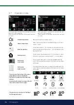
This menu is the system’s home screen. An overview of 

the current operational data is provided here. All other 

menus can be accessed from this menu. Depending 

on which system is defi ned, the following symbols may 

appear on the start menu, for example:

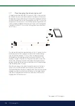
Main menu; display start menu.

Heating/Cooling

Settings for raising or lowering the temperature indoors and for scheduling temperature 

changes. Submenus for "Active Cooling" are shown if defi ned.

DHW

Settings for DHW production.

Ventilation

Settings for ventilation mode if the system includes a separate ventilation unit.

Operation data

This shows current and historical operational data for the system.

Installer

This is where the installer confi gures the settings and service for your system. 

Indoor temperature.

Displays the current indoor temperature for each heating circuit if room sensors have been 

installed.

Tank temperature

Shows the current temperature in the DHW tank.

Outside Temperature

Shows the outdoor temperature.

Summary of Contents for EcoLogic L

Page 1: ...tainable energy solutions worldwide 162 505 61 2 2021 02 25 Important Read carefully before use keep for future reference Translation of the original instructions Installation and Maintenance Manual CTC EcoLogic L M ...

Page 2: ......

Page 3: ...162 505 61 2 2021 02 25 Installation and Maintenance Manual CTC EcoLogic L M ...

Page 4: ... 10 Define_____________________________________________________________76 4 11 Service____________________________________________________________93 5 Parameter list ______________________________________________________ 99 6 Operation and Maintenance ____________________________ 101 7 Troubleshooting Appropriate measures______________________________________ 102 7 1 Information messages _________...

Page 5: ...ol system that monitors and controls your entire heating circuit regardless of how you choose to tailor it Congratulations on buying your new product CTC EcoLogic has a control system that monitors all DHW and heating circuit functions monitors and controls your heat pump solar panels additional heat buffer tank pool etc allows for individual settings indicates desired values for instance temperat...

Page 6: ...ion 20190620 or later Register your product for warranty and insurance purposes on our website https www ctc heating com customer service warranty registration No liability is accepted for any misprints We reserve the right to make design changes For your own reference Fill in the information below It may come in useful if anything should happen Product Serial number Installer Name Date Tel no Ele...

Page 7: ...y qualified persons in order to avoid a hazard Safety valve check Safety valve for boiler system to be checked regularly The product must not be started if it is not filled with water instructions are in the Pipe installation section WARNING Do not switch on the product if there is a possibility that the water in the heater is frozen This device can be used by children from the age of eight years ...

Page 8: ...nents 1 1 1 Printed circuit board PCB The images below show important components when connecting the CTC EcoLogic Supplied with CTC EcoLogic L Accessory pack available for CTC EcoLogic M A Circuit board power supply B Connection 230 V C Terminal block low voltage D Communication display unit relay extension card E Communication heat pump F USB port G BMS connection H Network connection Ethernet I ...

Page 9: ... Scope of delivery The figure below shows the main components in the EcoLogic delivery K Base unit L Electrical connection box communication cable display unit M Display unit N Room sensor O Outdoor sensor P 3 x Primary flow sensors 22k ...

Page 10: ...e schematic diagrams for System Types 1 to 6 in the Pipe installation chapter the control system measures the temperature in the heating circuit each minute Once a certain cumulative heat loss measured in degree minutes is measured the heat pump is started up to compensate for the loss Degree minutes refers to the product of the cumulative heat loss in degrees C and the time measured for this in m...

Page 11: ...ed from the heat pump as this is a more advantageous operation for the compressor The heat pump therefore only heats to the temperature required by the heating circuit This is economical in terms of the service life of the compressor and in maximising operating economy Buffer Tank System Types 4 6 If a buffer tank is connected see the schematic diagrams for Systems Types 4 to 6 in the Pipe Install...

Page 12: ...ccurs a large heat pump is switched on at the same time as a small heat pump is switched off and vice versa when reducing power Within both the small and large groups reciprocal heat pump operation is prioritised according to accumulated operation time When combining different types of heat pumps air water and ground source pumps are prioritised according to the current outdoor temperature 1 3 1 3...

Page 13: ...from the heat pump will vary depending on the operating conditions during the year When the outdoor temperature is less than 2 C the charge pumps must start in order to protect against frost in cases where an air water heat pump is installed A speed controlled charge pump will only work at 50 of its maximum capacity This provides for increased savings on the charge pump s operating economy In addi...

Page 14: ...at a certain time after heat loss occurs in the tank The factory setting is 180 minutes 1 5 1 Wood boiler In system 1 CTC EcoLogic can be connected to a wood boiler When wood firing is started and the flue gas sensor reaches the value set in the Installer Settings Additional Heat Start Flue Gas C menu factory set to Off the control activates the Wood operation status When wood operation is active ...

Page 15: ...p will reduce the flow When the DHW tank temperature increases or the solar panels drop in temperature and the temperature difference becomes 3 C factory setting the charging stops and does not start again until the temperature is at least 7 C warmer than in the DHW tank If both the DHW tank and buffer tank are defined the DHW tank is prioritised Charging first takes place to the DHW tank once the...

Page 16: ...e charging to start refer to the Installer Settings Solar Panels dT Max Bedrock C menu When the difference between the temperature in the solar panels and the brine circuit falls to 30 C the charging is stopped If the brine circuit temperature becomes warmer than the set value recharging will also be interrupted as the temperature then becomes too high for the heat pump to work refer to the Instal...

Page 17: ...mperature from which cooling will be permitted among other things can be set 1 9 Pool For System Types 4 to 6 the pool can be connected in parallel with the heating circuit via a heat exchanger in order to separate the liquids Fan convector Only applies to CTC EcoLogic L Via a sensor in the pool the pool s charge pump starts and stops in order to maintain the set temperature in the pool factory se...

Page 18: ...When switching from heating to cooling Heating is deactivated Delay until cooling is allowed see menu Installer Settings Cooling When switching from cooling to heating Heating is activated Cooling and heating cannot be active at the same time Separated heating cooling tank Cooling and additional heat sources cannot be active at the same time 1 10 2 EcoLogic System 5 Common and separated heating co...

Page 19: ...ts must be installed during active cooling Sensor B61 in cooling tank Return sensor B73 Primary flow sensor 3 B3 When separated heating cooling the system is regulated with B3 3 way valve heating cooling Y61 With separate heating cooling tank and to bypass additional heat 3 way valve cooling relay Y62 To avoid heat loss from the heat tank in a separate heating cooling tank system The external cont...

Page 20: ...r temperature exceeds or is equal to the temperature from which cooling is to be permitted see the Cooling permit from outdoor T ºC menu For systems with common heating cooling tank the delay time has passed after the production of heat has ended see menu bar Heating off delay Room sensor installed If a room sensor has been installed active cooling is permitted if the following criteria are met at...

Page 21: ...the minimum primary flow temperature Mixing valve control is calculated from the current and estimated primary flow temperature 1 10 3 2 Alarm logic cooling An alarm is triggered if The cooling flow temperature is lower than the set value factory setting 18 ºC minus 0 5 ºC The value is set on the menu bar Min flow temp cooling or For a common system the primary flow temperature is lower than the r...

Page 22: ...alues for the Heating Curve You define the heating curve yourself for your property by setting two values in the product control system This is achieved by selecting the options Inclination or Adjustment under the Installer Settings Radiator system menu Ask your installer to help you set these values It is extremely important to set the heating curve and in some cases unfortunately this process ma...

Page 23: ...rther adjustment is required i If the values set are too low this may mean that the desired room temperature is not being reached You then need to adjust the heating curve as necessary following the method shown above When the basic values have been set more or less correctly the curve can be finely adjusted directly using the Room temp shown on the home menu screen Appropriate Default Values Duri...

Page 24: ...ow Temperature Primary Flow Temperature Primary Flow Temperature Outside Temperature Outside Temperature Heating off out Outside Temperature Adjustment The curve can be parallel displaced adjusted by the desired number of degrees to adapt to different systems houses An example Inclination 60 C Adjustment 0 C In this example the maximum outgoing primary flow temperature is set at 55 C The minimum p...

Page 25: ...tomatically at 18ºC as Heating mode is set to Auto Heating mode Auto Auto On Off Auto means automatic On means that the heating is on For systems with a mixing valve and a radiator pump the mixing valve operates to the primary flow setpoint and the radiator pump is on Off means that the heating is switched off For systems with a radiator pump the radiator pump is switched off Heating ext mode Auto...

Page 26: ... 1309 90 1347 100 1385 120 1461 140 1535 504 x 276 x 122 mm 3 Technical data Supply Max fuse size Total max load CTC EcoLogic Max load relay output Electrical data 3 way valve Electrical mixing valve motor Output additional heat external additional heat source E1 E4 Sensor protective extra low voltage NTC 22k C ohm Discharge sensor type NTC 3 3 C ohm Outdoor sensor type NTC 150 C ohm Solar panel s...

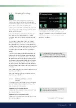
Page 27: ...ll other menus can be accessed from this menu Depending on which system is defined the following symbols may appear on the start menu for example Main menu display start menu Heating Cooling Settings for raising or lowering the temperature indoors and for scheduling temperature changes Submenus for Active Cooling are shown if defined DHW Settings for DHW production Ventilation Settings for ventila...

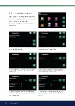
Page 28: ...rectional arrow 5 Specify whether Heat pump 1 is permitted or blocked For Permitted press plus For Blocked press minus Confirm with the right directional arrow 2 Verify that the system is filled with water Confirm with OK and the right directional arrow 1 Choose language Press OK to confirm 3 Select the system type using the plus minus buttons Confirm with the right directional arrow 4 Use the but...

Page 29: ...mporarily be deselected during the firing process EcoLogic provides heating to the radiators using the set heating curve The radiator thermostats reduce the heating supplied to the section of the house where a fire is burning When holiday reduction is activated H appears after the brackets e g 24 25 H When night reduction is active NR appears after the brackets e g 24 25 NR i The radiator thermost...

Page 30: ...1 Night Reduction function is assigned to Weekly Program 1 Night reduction means lowering the indoor temperature either via remote control or during scheduled periods In the menu HC Night reduction menu the periods during the week for night temperature reduction can be scheduled The value by which the temperature is lowered during the period is set in one of the following menus Room sensor install...

Page 31: ...days that you want the set temperature to be consecutively reduced For example if you want to go on holiday The value by which the temperature is lowered during the period is set in one of the following menus Room sensor installed Installer Settings Heating circuit Room temp lowered Holiday C Room sensor not installed Installer Settings Heating circuit Primary flow lowered Holiday C Holiday reduct...

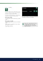
Page 32: ... function is activated by setting the number of hours using the plus sign in the Hot Water menu the heat pump immediately starts to produce extra DHW It is also possible to remotely control or schedule hot water production according to specified times DHW mode You set the values for this option which apply to the heat pump s normal operation There are three modes 4 4 1 Extra DHW You can use this m...

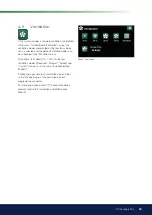
Page 33: ...e defined ventilation modes can be scheduled in the Ventilation menu The exhaust fan speed 10 100 for the four ventilation modes Reduced Normal Forced and Custom can be set in the menu Installer Settings EcoVent Scheduling is possible for all ventilation modes Refer to the Weekly Program chapter to learn about programming schedules For more information on the CTC EcoVent ventilation product refer ...

Page 34: ...ow keys or click where the cursor is in the example 4 6 2 Setting a weekly program A weekly program can be set for most remotely controlled functions in the menus under Installer Settings However schedules for Night reduction Extra DHW and Ventilation can only be accessed via the start menu The schedule includes 30 rows and a setting can be made in each row For example in one row you can set the d...

Page 35: ...ram for Night Reduction the temperature reduction that will apply during the period is specified in C here instead When a temperature is specified setting range 1 to 30 C the status of the row automatically switches to On When setting a SmartGrid schedule the SmartGrid function SG Blocking SG Low price and SG Overcapacity is specified in the Action row The status of the row automatically switches ...

Page 36: ...p liquid to water The liquid to water heat pump is connected and defined for the circuit The in and out temperatures of the heat pump are shown on the right The icon bar at the bottom of the menu page displays icons for additional functions or subsystems that have been defined Scroll using the arrows or swipe in the list if not all the icons fit on the page Ventilation Pool Solar panels Wood boile...

Page 37: ...HW HC DHW and heat are produced for the heating circuit HC Off No heating takes place The menu shows current temperatures and other operational data for CTC EcoLogic Status DHW Shows the various operational statuses refer to the table below Delay mixing valve 25 Shows the mixing valve delay for production of heat from the upper tank to the heating circuit Applies to System Type 6 Cooling tank C 0 ...

Page 38: ...heating circuit to the heat pump Room temperature C 21 22 Shows the room temperature for the current heating circuit and the setpoint in brackets if room sensor installed Radiator pump Off Shows the operational status of the radiator pump On or Off Mixing valve Opens Shows whether the mixing valve opens or closes the heat supplied to the heating circuit This menu bar is displayed for System Types ...

Page 39: ...nu Communication error HP The control unit cannot communicate with the heat pump On DHW The heat pump heats the DHW tank Off start delay The heat pump s compressor is off and is prevented from starting due to the start delay Off start ready The heat pump s compressor is off but ready to start Flow on Displayed if there is flow in the charging coil On cooling The heat pump is producing cooling for ...

Page 40: ...ut C 4 0 1 0 This shows the brine pump s incoming and outgoing temperatures This menu bar is displayed for liquid to water heat pumps Fan On 80 Shows operating status of the fan On or Off and the fan speed in percent This menu bar is displayed for air to water heat pumps HP in out C 35 0 42 0 Shows the heat pump s incoming and outgoing temperatures 4 7 4 Operation data Compressor HP The menu shows...

Page 41: ...en powered Max primary flow C 51 Shows the highest temperature that has been supplied to the heating circuit El heat kWh 250 Shows how much additional heat has been used Energy output kWh 10000 Shows total energy output The value is only shown for language choice Norwegian and German The value is not calculated for CTC GSi 600 CTC EcoPart 600 CTC EcoAir 600 these have a value of 0 Operation time 2...

Page 42: ... Comfort In the Installer Define System Type menu the heat pump s must be defined in the Heat pumps for DHW row The heat pump in the Installer Define Heat pump menu must be set to On Flue gas C 150 Shows the temperature of the flue gas flow Applies to System Type 1 Mixing valve Open Displayed if the mixing valve for additional heat opens or closes Click additional heat source E1 E3 to view detaile...

Page 43: ...he additional heat source Applies to System Types 1 3 Delay add heat 180 The menu displays the required delay in minutes of subnormal temperature in the buffer tank before additional heat E1 is started Applies to System Types 4 6 Additional heat E2 0 Shows the output signal 0 10V or how many steps 0 3 or 0 7 of E2 are active EcoMiniEl E3 0 Shows the number of active steps 1 3 for additional heat E...

Page 44: ...e Extra DHW function is active DHW circulation Off On means the DHW circulation function is active DHW tank ext C 45 Shows the temperature in the external DHW tank if defined When the Legionella protection function is active L is displayed e g 45 60 40 L Pump ext DHW tank On Displays the status On Off of the charge pump for the external DHW tank if defined Status E4 Off Shows the operational statu...

Page 45: ...Grid Off The status of the SmartGrid functions for Buffer Tank Off SG Low Price SG Overcapacity is shown here Add heat E1 Off Here you can see if the additional heat source is On or Off Delay add heat 0 Here you can see the time minutes before the additional heat E1 goes to the On position 4 7 8 Operation data Buffer Tank Operation Data External Buffer Tank menu Status Buffer tank DHW The heat pum...

Page 46: ... This shows the operating mode for the pump Off or On for recharging the bedrock ground Valve charge brine loop Off This shows the operating mode for the valve Off or On for recharging the bedrock ground Energy output kWh 0 Shows total estimated energy output Energy output kWh 0 0 Shows energy output in the last 24 hours Power kW 0 0 Shows current power extraction 4 7 9 Operation data Solar panels...

Page 47: ... water DHW HC Wood boiler producing heat for the heating circuit HC Wood Wood operation active Wood operation is activated when the flue gas temperature exceeds the set value and the temperature is equal to or above its reference value setpoint When wood operation is active the heat pump or additional heat is not used for heating Wood operation is also activated when the primary flow sensor B1 is ...

Page 48: ... Externally Blocked means that pool heating has been blocked from the Installer Settings Pool menu Blocked Externally means that the pool is externally blocked via remote control or a weekly program Pool temp C 21 22 Shows the temperature in the pool and the setpoint that the system is working to achieve SmartGrid Off The status of the SmartGrid functions for Pool Off SG Low Price SG Overcapacity ...

Page 49: ...40 Highest measured value for humidity Displayed if rH sensor from the CTC SmartControl series is installed Refer to the Installation and Maintenance Manual for the CTC SmartControl accessory Highest level CO2 550 Highest measured value for carbon dioxide ppm Displayed if the CO2 sensor from the CTC SmartControl series is installed Refer to the Installation and Maintenance Manual for the CTC Smart...

Page 50: ...ings can be carried out from this menu 4 8 1 Setting the time Time and Date Click on the time symbol The menu can also be accessed by clicking the date or time in the upper right corner of the start screen Press OK to highlight the first value and use the arrows to set the time and date DST On Active The left value can be set On means the time is adjusted according to Summertime The right value is...

Page 51: ...alarm sounds Time zone GMT 1 12 14 Set your time zone relative to GMT Lock code 0000 Press OK and use the arrows to set a 4 digit lock code If a lock code is set it is shown as four stars You will be prompted to enter the code when the screen is restarted NB Make a note of the lock code for your own reference when you enter it in the menu for the first time The serial number of the display 12 digi...

Page 52: ...ng season and summer mode can take place automatically Auto or a selection can be made here to set the heating to On or Off Auto switching the heating season On and Off carried out automatically On Continuous heating season the radiator pump circulates constantly Off there is no heating the radiator pump does not run is turned over Heating mode ext Auto On Off The heat mode selected in this menu c...

Page 53: ...again heat to the house is permitted when the temperature falls below or equals the set value in the Heating off outdoor C menu for the number of minutes set in the Heating off time menu Inclination C 50 25 85 Inclination means the temperature your property needs at different outdoor temperatures More information about this can be found in the Your home s heating settings chapter The value set in ...

Page 54: ...ring holidays can be set here Night reduction can also be set periodically the temperature decrease is then entered in the weekly program Heating circ pump speed 100 Off 1 100 If radiator pump G1 is connected this setting will be Off The purpose of this menu is to set the speed of the heat pump s charge pump G11 The menu bar is displayed for System Type 1 as well as System Types 2 and 3 if there i...

Page 55: ...temperature setpoint is reduced to 25 C in daily 5 C stages The final step may be less than 5 C Following the stepped decrease and 1 day at the setpoint of 25 C the value is calculated automatically according to Your home s heating settings Mode 3 In this mode the function starts in Mode 1 followed by Mode 2 and lastly by Your home s heating settings Drying period temp C 25 25 55 The temperature f...

Page 56: ...low HP Add heat diff C 14 5 20 If the actual value for the primary flow is less than or equal to the setpoint minus the set value the degree minutes are set to the highest set start value for the peak heat factory set to 500 Applies to System Types 1 2 and 3 Diff between comp 60 200 30 This menu defines the difference measured in degree minutes at which the heat pumps will be started if necessary ...

Page 57: ...ls prioritisation during DHW production between the air to water and liquid to water heat pumps if both types are connected to the system The default value is 7 C which means that the air to water heat pump is prioritised for outside temperatures from 7 C and warmer SmartGrid block HP No No Yes Read more in the Remote Control SmartGrid section of the Installer Define chapter Heat pump 1 Apply sett...

Page 58: ...limit 20 0 20 Temperature limit for summer power When the outdoor temperature is equal or higher T1 the compressor speed is adjusted down to speed R1 The heat pump starts and stops at the actual value and setpoint value Only applies to modulating air to water heat pumps Max rps warm temp 50 50 120 The maximum permissible speed of the compressor at summer temperature Sets the compressor s maximum s...

Page 59: ...riff HP No No Yes Yes means the function can be activated via remote control Read more in the Def Remote Control section of the Installer Define chapter Tariff HP schedule This menu bar is displayed if a weekly program has been defined for the HP Tariff function For more information refer to chapter Weekly Program for schedule setting section Def Remote Control of the Installer Define chapter for ...

Page 60: ...define the difference in degree minutes between the start and stop conditions for the electric boiler If the electric boiler is started at 500 degree minutes it will be stopped at 400 degree minutes based on a difference setting of 100 Applies to System Types 2 and 3 Add heat EcoMiniEl No No 1 2 3 This menu bar is displayed if EcoMiniEl is defined Specify whether the electric heater should connect...

Page 61: ...nu is used to specify the number of minutes of subnormal temperature in the buffer tank after which EcoMiniEl is required to start Applies to System Type 4 if steps 1 2 3 are selected in the Additional heat EcoMiniEl menu Delay EcoMiniEl step 30 10 120 This menu is used to specify the delay step with which EcoMiniEl is required to start Applies to System Type 4 if steps 1 2 3 are selected in the A...

Page 62: ... control Read more in the Remote Control Tariff EL section of the Installer Define chapter Tariff EL schedule This menu bar is displayed if a weekly program has been defined for the Tariff EL function For more information refer to chapter Weekly Program for schedule setting section Def Remote Control of the Installer Define chapter for defining the remote control function Start at flue gas C Off O...

Page 63: ...s menu is used to set the negative hysteresis before the heat pump starts charging the DHW tank after the setpoint has been reached Example If the stop temperature is 55 C and hysteresis is set to 5 C in this menu it means the heat pump will start DHW charging again when the temperature in the tank has dropped to 50 C Max time DHW min 20 5 60 This specifies the maximum time for which the heat pump...

Page 64: ...uring DHW charging If No is selected the additional heat is blocked Add heat DHW E2 3 No 1 10 If Yes is selected additional heat is active during DHW charging If No is selected the additional heat is blocked Add heat DHW EcoMiniEl 3 No Step 1 3 If Step 1 3 is selected additional heat is active during DHW charging If No is selected the additional heat is blocked Min temp C 45 20 55 This menu is use...

Page 65: ... periods of DHW circulation Displayed if DHW circulation has been defined in the Installer Define DHW tank menu Diff start ext DHW tank 5 3 15 These menu bars are displayed if External DHW Tank has been defined in the Installer Define DHW Tank menu This menu is used to select the temperature difference at which the charging of the external DHW tank is required to start The difference is specified ...

Page 66: ...Both SmartGrid A and SmartGrid B must be defined in the remote control menu for this menu to be displayed Read more in the Def Remote Control SmartGrid A B section of the Installer Define chapter SmartGrid Overcapacity C 10 Off 1 30 Setting to increase temperature at energy price Overcapacity via SmartGrid Both SmartGrid A and SmartGrid B must be defined with a remote control input for this menu t...

Page 67: ... chapter for defining the remote control function Buffer tank schedule This menu bar is displayed if a weekly program has been defined in the Buffer Tank row in the Installer Define Remote Control menu For more information refer to chapter Weekly Program for schedule setting section Def Remote Control of the Installer Define chapter for defining the remote control function SmartGrid Low Price C 10...

Page 68: ...m Type 1 Max DHW tank C 85 10 95 The maximum permitted temperature in the DHW tank Charging stops once the set temperature has been reached Max buffer tank C 85 10 95 The maximum temperature in the buffer tank Charging stops once the set temperature has been reached Max temp brine C 18 1 30 Setting for maximum permitted brine temperature Solar charging of the borehole ceases when this value has be...

Page 69: ...ar Test function should perform With 0 as the set value solar test takes place continuously Winter mode Off Off On Deactivate the Solar test tank min function Off means only borehole charging Flow l mln 6 0 0 1 50 0 The flow circulating through the solar panels should be indicated here This can be read from the flow meter in the system unit The flow should be read when pump G30 is running at 100 N...

Page 70: ...nks allowed to exceed 95 C Recooling No Yes No This option can be activated when the emergency cooling function has been activated The function means that the system endeavours reduce the temperature in the DHW and buffer tank to the set setpoint set in the Re cooling to temp menu This means that the solar panels are used as cooling elements for a short period of time Recooling to temp C 70 50 80 ...

Page 71: ... 1 5 The setpoint increase for pool heating when SmartGrid Overcapacity is active can be set here Read more in the Installer Define Remote control SmartGrid menu Block pool On Off On This function is used to block external pool heating This menu bar is displayed if the criteria below are met the pool is connected defined to the system a remote control input has been defined for the Pool function a...

Page 72: ...en blocked see menu bars Ext Block cooling and Block cooling schedule until the production of cooling is permitted again Diff delay calc 10 1 600 Set how often minutes a new value for the primary flow temperature is calculated based on the measured return temperature of the cooling flow Start cooling at overtemp C 1 0 0 5 15 0 The menu bar is displayed if passive cooling and room sensors have been...

Page 73: ... SmartGrid have been defined in the Installer Define Remote Control menu Read more in the Remote Control SmartGrid section of the Installer Define chapter Ext block cooling Yes Yes No Blocking cooling can be remote controlled remotely For example the function can be used to turn off cooling with the help of a humidity sensor when there is a risk of condensation This menu bar is displayed if the cr...

Page 74: ...connection speed is 100 mbit 4 9 10 2 Settings BMS MB address 1 1 255 Adjustable 1 255 Baudrate 9600 9600 19200 Possible settings 9600 or 19200 Parity Even Even Odd None Possible settings Even Odd or None Stop bit 1 1 2 Possible settings 1 or 2 Modbus TCP Port 502 1 32767 This menu bar is displayed if Modbus TCP is defined in the Ethernet row in the Installer Define Remote Control menu 4 9 10 3 My...

Page 75: ... current The compressor and electrical output are blocked when round circulation is active This menu bar is displayed if a weekly program has been defined for the Round circulation function The Round circulation function can also be controlled remotely by activating the Input defined for the function For more information refer to chapter Weekly Program for schedule setting section Def Remote Contr...

Page 76: ...he USB drive is installed The rows show the date and time of saved settings Press OK to confirm 4 9 16 Load settings The saved settings can be recovered Press OK to confirm 4 9 17 Load Factory settings The product is supplied with the factory values set Saved settings in Bank 1 3 are deleted when factory settings are restored The selected language is recovered Press OK to confirm ...

Page 77: ...is used in systems 2 3 and 4 Heating Circuit 2 cannot be installed because mixing valve Y2 is used to mix additional heat Also note that the EcoLogic System Type 5 has no mixing valve for additional heat E1 EcoMiniEl E3 No Yes No Specify whether EcoMiniEl is connected This menu bar is displayed if System Type 2 3 or 4 is defined Additional heat E2 No No 0 10V 0 3 steps 0 7 steps Specify whether ad...

Page 78: ...connection are present If Yes a degree minute calculation will also be performed during DHW charging This menu bar is displayed if System Type 2 or 3 is defined 4 10 2 Def Remote control This chapter describes all remote control functions how they are set up and how they are used The Installer Define Remote Control menu defines how the remote control inputs should be activated by specifying one of...

Page 79: ...lly Closed NC Define a normal mode for the external control signal NO or NC The setting is made for the current heating circuit in the Installer Define Heating Circuit menu For example a two way switch can be connected to the defined input If the button when used generates a control signal on the input circuit closes the circuit shall be defined as NO When the circuit closes and the control signal...

Page 80: ...he Night Reduction Temperature section in the Room Temperature chapter Heating mode ext HC1 Off K22 K25 Channel 1A 7B BMS DI0 7 Switching between heating season and summer season can take place at a specific outdoor temperature Auto or heating can be either always On or Off In the Installer Define Remote Control menu specify an Input for the remote control function In the Installer Define Heating ...

Page 81: ... Input for the remote control function In the Installer Define DHW Tank menu configure the normal mode for the external control signal Normally Open NO Normally Closed NC Setting extra DHW production to start immediately can also be done in the DHW menu The weekly program for extra DHW can also be set in this menu For more information refer to the Extra DHW section in the DHW chapter Block Cooling...

Page 82: ...eriods when the electricity rate is higher In the Installer Define Remote Control menu specify an Input for the remote control function In the Installer Settings Additional Heat menu set remote control mode Yes in the Tariff EL row Access function scheduling from the Tariff EL row For more information refer to the Additional Heat Tariff EL section in the Installer Settings chapter Round circulatio...

Page 83: ...ating buffer tank Off K22 K25 Channel 1A 7B BMS DI0 7 The buffer tank helps to maintain a more even temperature in the heating circuit In the Installer Define Remote Control menu specify an Input for the remote control function In the Installer Define Buffer Tank menu configure the normal mode for the external control signal Normally Open NO Normally Closed NC in the Buffer tank ext config row In ...

Page 84: ...al heat passive cooling pool DHW tank upper tank and lower tank The factory set temperature changes setpoints that apply when Low Price mode and Overcapacity mode are activated are shown in brackets below Heating circuit 1 SmartGrid Low Price C room temp or primary flow temp 1 C SmartGrid Overcapacity C room temp or primary flow temp 2 C Heat pump SmartGrid block HP Additional heat SmartGrid block...

Page 85: ...nt Normal Vent Forced Vent Custom Vent Absent Off K22 K25 Channel 1A 7B BMS DI0 7 When there is a signal in the respective ventilation function s remote control input the selected ventilation mode will start and be active for half an hour In the Installer Define Remote Control menu specify and Input for current ventilation functions Click the Ventilation symbol in the start menu to access the Vent...

Page 86: ...configure the normal mode for the external control signal Normally Open NO Normally Closed NC in the Noise reduction ext config row In the Installer Settings Heat Pump Heat Pump 1 menu in the Ext Noise reduction rps row set the compressor speed value applicable for remote control For more information refer to the Heating Pump section in the Installer Settings chapter HP Silent Mode 1 Off K22 K25 C...

Page 87: ...ess connection Wireless Select Wireless to connect CTC s wireless room sensors to the heating circuit Refer to the CTC Wireless Room Sensor manual for information on how to connect these sensors SmartControl SmartControl is a separate series of wireless accessories If SmartControl is selected the connection channel must be selected in the row below SmartControl accessories are connected to the sys...

Page 88: ...e control is defined for the Flow level switch function in the Installer Define Define Remote Control menu 4 10 4 1 Def heat pump 1 Noise reduct ext config NC None NC NO This menu bar is displayed if an Input for remote control is defined for the HP Noise Reduction function in the Installer Define Remote Control menu Tariff HP ext config NC None NC NO This menu bar is displayed if an Input for rem...

Page 89: ...e external control signal when remotely controlling the function For examples of normal mode settings refer to the Def Remote Control section of the Installer Define chapter 4 10 7 Def Heating buffer tank Heating buffer tank ext config NC None NC NO This menu bar is displayed if System Types 2 6 are selected in the Installer Define System Type menu System Type 1 does not include the buffer tank Th...

Page 90: ...ssories If SmartControl is selected the connection channel must be selected in the row below These accessories must be connected to the heating circuit via the Installer Define SmartControl menu Refer to the separate Installation and Maintenance Manual for the SmartControl accessory Block cooling ext config None None NC NO This menu bar is displayed if an Input for remote control is defined for th...

Page 91: ...coVent Ventilation Yes Yes No This defines whether the EcoVent ventilation product is to be connected to the system The menus below define the Normally Open NO or Normally Closed NC mode for the external control signal when remotely controlling the function This menu bar is displayed for the functions for which an Input for remote control is defined Vent red ext config None None NC NO Setting for ...

Page 92: ...he solar energy heat should be supplied DHW tank only Only DHW buffer tank only Only Buffer hot water and buffer tank VV and buffer boiler only Boiler If this is selected the solar panels will pre heat the hot water in the boiler Only shown for System Type 1 Vacuum No Yes No Specify whether the solar panels are vacuum or flat solar panels Borehole recharge Y31 G31 No Yes No There is an option of r...

Page 93: ...For more information about the SMS function refer to the Installation and Maintenance Manual for CTC SMS 4 10 14 Def SmartControl SmartControl is a separate series of wireless accessories SmartControl No Yes No If Yes is selected SmartControl accessories can be connected to the heating circuit Refer to the connection procedure in the separate SmartControl Accessories manual 4 10 15 Def Current sen...

Page 94: ...rrect operation are the pressure sensors and the electric heater s overheating protection device The heat pump returns to normal operation after 10 minutes of inactivity or when exiting the Function Test menu When the menu is opened all automatic functions are stopped and testing can be performed 4 11 1 1 Test Heating Circuit If several heating circuits have been installed they will all be display...

Page 95: ...er Heating Cable Off Off On Function test heating cable 4 way valve Y11 Off Off On Function test 4 way valve Y11 Fitted to air to water HP 4 11 1 3 Test Valves The following valves are function tested from this menu 3 way valve Y21 Down Up Down 3 way valve Y22 Down Up Down 4 11 1 4 Test Additional Heat Connected additional heat sources E1 E4 are tested here Relay Output E1 Off On Off Switches the ...

Page 96: ... pump to full speed rpm Solar heat exchanger pump G32 0 0 100 Tests the solar heat exchanger pump up to full speed rpm Solar 3 way valve Y30 DHW DHW HC Tests the two modes on the valve flow to DHW tank or buffer tank Solar charge borehole Y31 G31 Off On Off Tests the 3 way valve Y31 and solar heat exchanger pump G31 Pool pumps and valve G50 G51 Off On Off Tests the pool pumps and valve G50 G51 4 1...

Page 97: ...r further troubleshooting For alarms related to the heat pump values can be displayed from sensors for pressure HT LT temperature OP and current I 4 11 3 Alarm dumps Export the alarms displayed in the alarm log to a USB drive A dump can consist of one or more alarms as well as specific values before and after the alarm was triggered 4 11 4 Settings coded This menu is intended to set the manufactur...

Page 98: ... USB drive or online The rows are greyed out until the USB drive is installed or the display is connected to the internet Click OK to confirm the upload The settings are retained during updating but the old values are overwritten by any new factory values 4 11 7 Write log to USB Intended for service engineers This function can be used to save logged values to a USB memory stick 4 11 8 Re installat...

Page 99: ...Room temperature 4 C B14 0 0 3 0 3 0 Correction of room sensor B14 Outdoor temperature C B15 0 0 3 0 3 0 Correction of outdoor sensor B15 Out from solar panels C B31 0 0 3 0 3 0 Correction of temperature sensor on solar panels for outgoing temperature In to solar panels C B30 0 0 3 0 3 0 Correction of temperature sensor on solar panels for incoming temperature 4 11 10 Set address In this menu heat...

Page 100: ...ps 90 Warm temp limit 20 Max rps warm temp 50 Ext noise reduction rps 50 Noise reduction schedule Compressor stop at brine C 5 Factory setting Brine pump Auto Tariff HP No Tariff HP schedule Passive cooling brine pump on Yes Silent mode schedule Additional heat Start E1 degree minutes 500 Diff E1 degree minutes 100 Start E2 degree minutes 500 Diff E2 degree minutes 100 Add heat EcoMiniEl No Start ...

Page 101: ...de No Flow l mln 6 0 Protection collector Max temp C 120 Cooling Yes Recooling No Recooling to temp C 70 Anti freeze No Anti freeze C 25 Factory setting Pool Pool Blocked Pool temp C 22 Pool diff C 1 0 Pool priority C Low SmartGrid Low Price C 1 SmartGrid Overcapacity C 2 Block pool Off Block pool schedule Cooling Room temp cooling C 25 0 Cooling permit from outdoor T Off Active delay 10 Heating o...

Page 102: ...m sensors or when using an fireplace or open stove The alarm LED on the room sensor still functions as normal If you use the fire or open stove only occasionally the firing process can affect the room sensor and reduce the temperature supplied to the radiators It can then get cold in the rooms in other parts of the house The room sensor can temporarily be deselected during the firing process CTC E...

Page 103: ... be fully open in the area where the room sensor is located A correctly operating heating circuit is important to the heat pump s operation and affects energy savings When adjusting the system always do so with all radiator thermostats fully open The thermostats can be individually adjusted after a few days in the other rooms If you do not achieve the set room temperature check That the heating ci...

Page 104: ...ed the ground loop may not be large enough or there may be a fault with the sensor Check the brine circuit temperature in the Current operation data menu If the incoming temperature falls below 5 C during operation call in a technician to inspect the brine circuit Motor protection CTC EcoLogic constantly monitors the compressor s operating current and an alarm is triggered if the compressor is dra...

Page 105: ...t pump I010 Tariff EL Off Shows that tariff has switched off the immersion heater elements I003 Compressor blocked The compressor is set to be shut down e g before drilling or digging has been carried out for the collector coils The product comes with the compressor switched off This option is selected in the Installer Settings Heat Pump menu I021 HC1 Ext Ctrl Heating I022 HC2 Ext Ctrl Heating I02...

Page 106: ...An alarm is displayed if a fault occurs with a sensor that is not connected or has short circuited If this sensor is significant to the system s operation the compressor stops This requires the alarm to be reset manually after the fault has been rectified E002 Sensor B9 Boiler E031 Primary flow sensor 1 B1 E007 Sensor buffer tank B6 E032 Primary flow sensor 2 B2 E012 Sensor DHW tank B5 E033 Primar...

Page 107: ...the motor protection A4 E044 Stop high compr temp This message appears when the compressor temperature is high Press reset and check whether the alarm recurs If the fault recurs contact your installer E045 Stop low evaporation This message appears when the evaporation temperature is low Press reset and check whether the alarm recurs If the fault recurs contact your installer E046 Stop high evapora...

Page 108: ... volume in the system may be too low The flow may be too low Applies to EcoAir E163 Defrost max time duration The heat pump has not had time to complete defrosting within the maximum time Make sure that any ice on the evaporator has disappeared E087 Driver E088 Driver 1 E109 Driver 29 Driver fault E117 Driver Offline Press reset and check whether the alarm recurs If the fault recurs contact your i...

Page 109: ...rcuit to an existing boiler using a mixing valve The control system starts the boiler only as required as the mixing valve mixes in the additional heat The DHW is preheated in the boiler and then heated up in a separate DHW heater A flue gas sensor may be fitted to the boiler Solar energy can be connected to the boiler using a 3 way valve or diverted to recharge the bedrock ground Cooling can easi...

Page 110: ...he house protected from direct sunlight It is connected using a 2 core cable min 0 5 mm The room sensors B11 to B14 must be fitted in an open space in the property where a representative temperature is expected They are connected using a 3 core cable min 0 5 mm The primary flow sensors B1 to B4 must be placed on the primary flow of the respective heating circuit Return sensor B7 is placed on the r...

Page 111: ...information refer to the Installation and Maintenance instructions of the respective heat pump 8 1 3 System Type 1 DHW The DHW is preheated in the boiler by the heat pump and then heated up in a separate DHW heater DHW heater DHW circulation is obtained from the pump G40 Fresh DHW from the DHW heater is mixed in by the mixing valve and chilled water released down into the tank before once more bei...

Page 112: ...d signals to the control system that wood is being lit The sensor B9 should be fitted so that the boiler temperature is measured 8 1 5 System Type 1 Passive cooling If the Cooling function is defined mixing valve Y3 charge pump G3 and sensor B3 should be used for the cooling installation not heating circuit 3 For details on how to connect see the Installation and Maintenance instructions for the c...

Page 113: ...0 and sensors B30 and B31 are fitted next to the solar panels For recharging the bedrock ground a 3 way valve Y31 heat exchanger charge pump G31 and non return valve are connected The charge pump for recharging the borehole G31 ensures there is enough flow through the heat exchanger The speed controlled pump G32 and a heat exchanger are fitted for charging the DHW 8 1 6 System Type 1 Solar heating...

Page 114: ...e mixing valve Y4 is used to connect the tank to the system not to heating circuit 4 Solar energy can be connected either to the DHW tank or to the buffer tank using 3 way valves The solar energy can also be used to recharge the bedrock ground Cooling can easily be connected to the bedrock ground source heating circuit Heating circuit 4 Heating circuit 3 Heating circuit 2 Heating circuit 1 Fan con...

Page 115: ...ps 1 and 2 can be connected using 3 way valves that direct the flow either to the DHW system or the heating circuit The other heat pumps are connected to the heating circuit Solar heating can be connected either to the DHW tank or to a buffer tank using 3 way valves or to a ground heating coil Cooling can easily be connected to the bedrock ground source heating circuit Heating circuit 4 Heating ci...

Page 116: ... The outdoor sensor B15 must be fitted to the outer wall of the house protected from direct sunlight It is connected using a 2 core cable min 0 5 mm The room sensors B11 to B14 must be fitted in an open space in the property where a representative temperature is expected They are connected using a 3 core cable min 0 5 mm The primary flow sensors B1 to B4 must be placed on the primary flow of the r...

Page 117: ...gic while charge pumps G13 to G20 are controlled from their respective heat pumps Heat pumps 1 and 2 can be connected using 3 way valves that direct the flow either to the DHW system or the heating circuit If more heat pumps are installed these should be connected to the heating circuit The heat pumps are powered separately not through CTC EcoLogic Refer to the heat pump s Installation and Mainten...

Page 118: ... the tank before once more being heated up The non return valves are necessary to ensure that circulation proceeds as intended Control valves allow the desired flow of the circuit to be adjusted Option B illustrates the possibility of installing one or more DHW tanks which are then connected via a heat exchanger to the lower DHW tank shown in the figure This solution requires the installation of a...

Page 119: ...ixing valve Y2 is used to connect the additional heat to the system not to heating circuit 2 If the buffer tank is connected the mixing valve Y4 is used to connect the tank to the system not to heating circuit 4 Sensor B6 should be installed in the buffer tank Sensor B10 should be connected to measure the temperature coming from the additional heat System 2 DHW tank Additional heat DHW tank Heatin...

Page 120: ...olled pump G30 and sensors B31 and B30 are fitted next to the solar panels For recharging the bedrock ground a 3 way valve Y31 heat exchanger and charge pump G31 are connected The 3 way valve Y30 is fitted together with the speed controlled pump G32 and heat exchanger in order to direct the flow towards the DHW tank or the buffer tank Heat exchangers and pumps G32 do not need to be installed to th...

Page 121: ... 1 and 2 can be connected using 3 way valves that direct the heat flow either to the DHW system or the heating circuit The other heat pumps are connected to the heating circuit Solar heating can be connected either to the DHW tank or to a buffer tank using 3 way valves or to a ground heating coil Cooling can easily be connected to the bedrock ground source heating circuit Heating circuit 4 Heating...

Page 122: ... and 2 can be connected using 3 way valves that direct the flow either to the DHW system or the heating circuit The other heat pumps are connected to the heating circuit Solar heating can be connected either to the DHW tank or to a buffer tank using 3 way valves or to a ground heating coil Cooling can easily be connected to the bedrock ground source heating circuit Heating circuit 4 Heating circui...

Page 123: ...he outdoor sensor B15 must be fitted to the outer wall of the house protected from direct sunlight It is connected using a 2 core cable min 0 5 mm The room sensors B11 to B14 must be fitted in an open space in the property where a representative temperature is expected They are connected using a 3 core cable min 0 5 mm The primary flow sensors B1 to B4 must be placed on the primary flow of the res...

Page 124: ...3 way valves that direct the flow either to the DHW system or the heating circuit If more heat pumps are installed these should be connected to the heating circuit Be careful to ensure that the ports on the valves are installed correctly In system 4 the primary flow from heat pump 1 is connected to the additional heat as shown in the figure above The heat pumps are powered separately not through E...

Page 125: ... released down into the tank before once more being heated up The non return valves are necessary to ensure that circulation proceeds as intended Control valves allow the desired flow of the circuit to be adjusted Option B illustrates the possibility of installing a DHW tank s which is are then connected via a heat exchanger to the lower DHW tank shown in the figure This solution requires the inst...

Page 126: ...t the additional heat to the system not to heating circuit 2 Sensor B10 should be connected to measure the temperature coming from the additional heat In System type 5 the tip heat E1 is connected to the buffer tank The DHW tank can then be provided with additional heat E4 Heating buffer tank Additional heat DHW tank System 4 System 5 Heating buffer tank DHW tank If charge pump G11 is used for the...

Page 127: ...ng installation not heating circuit 3 For details on how to connect see the Installation and Maintenance instructions for the cooling installation Fan convector Pool Heating buffer tank 8 3 6 System Types 4 and 5 Pool The pool can be connected in parallel with the heating circuit Charge pump G50 and circulation pump G51 are connected with sensor B50 and the heat exchanger ...

Page 128: ...nected The 3 way valve Y30 is fitted together with the speed controlled pump G32 and heat exchanger in order to direct the flow towards the DHW tank or the buffer tank Heat exchangers and pumps G32 do not need to be installed to the solar heating circuit if there is already a loop in the connected DHW heating tank When the recharging function is in operation CTC EcoLogic also starts the brine pump...

Page 129: ...lar heating can be connected either to the DHW tank or to a buffer tank using 3 way valves or to a ground heating coil Cooling can easily be connected to the bedrock ground source heating circuit Heating circuit 4 Heating circuit 3 Heating circuit 2 Heating Circuit 1 Fan convector Solar panels Heating buffer tank Passive cooling Pool DHW tank Brine circuit CTC EcoLogic M system 6 does not include ...

Page 130: ...irect sunlight It is connected using a 2 core cable min 0 5 mm The room sensors B11 to B14 must be fitted in an open space in the property where a representative temperature is expected They are connected using a 3 core cable min 0 5 mm The primary flow sensors B1 to B4 must be placed on the primary flow of the respective heating circuit The sensor B7 is placed on the return flow from the heating ...

Page 131: ...d from their respective heat pumps Heat pumps 1 and 2 can be connected using 3 way valves that direct the flow either to the DHW system or the heating circuit If more heat pumps are installed these should be connected to the heating circuit Be careful to ensure that the ports on the valves are installed correctly The heat pumps are powered separately not through EcoLogic Refer to the heat pump s I...

Page 132: ...up The non return valves are necessary to ensure that circulation proceeds as intended Control valves allow the desired flow of the circuit to be adjusted Option B illustrates the possibility of installing one or more DHW tanks which are then connected via a heat exchanger to the lower DHW tank shown in the figure This solution requires the installation of an external DHW tank sensor B43 in the ex...

Page 133: ...sing a 4 way bivalent mixing valve Heating buffer tank DHW tank Additional heat 8 4 5 System Type 6 Passive cooling If the Cooling function is defined mixing valve Y3 charge pump G3 and sensor B3 should be used for the cooling installation not heating circuit 3 For details on how to connect see the Installation and Maintenance instructions for the cooling installation Fan convector ...

Page 134: ...onnected in parallel with the heating circuit as shown in the figure below Charge pump G50 and circulation pump G51 are connected with sensor B50 and the heat exchanger Heating circuit 4 Heating circuit 3 Heating circuit 2 Heating Circuit 1 Heating buffer tank Pool ...

Page 135: ... exchanger and charge pump G31 are connected The 3 way valve Y30 is fitted together with the speed controlled pump G32 and heat exchanger in order to direct the flow towards the DHW tank or the buffer tank Heat exchangers and pumps G32 do not need to be installed to the solar heating circuit if there is already a loop in the connected DHW heating tank When the recharging function is in operation C...

Page 136: ...136 CTC EcoLogic M L 9 Valves ...

Page 137: ...rom the energy source C Radiator primary flow to port AB on the diverting valve Primary flow The mixing valve motor is mounted on the valve with the knob in the centre position Connection as per 1 and 2 The motor must move in a clockwise direction to close increase decrease Connection as per 3 and 4 The motor must move in an anticlockwise direction to close increase decrease Energy source refers t...

Page 138: ...ersely right to left left to right The direction of the motor can be changed using the loop under the actuator cap The loop is always connected towards the heat pump 9 2 2 Diverting valve LK EMV 110 K When the motor transfers power to the black wire port A opens and port B closes Flow AB to A hot water production and Black is powered NB The valve must be turned around in order to change direction ...

Page 139: ...move in a clockwise direction to close increase decrease Valve cone setting for installation Applies when there is no heating needed The motor must move in a clockwise direction to close increase decrease 9 3 Bivalent mixing valve 9 3 1 Bivalent mixing valve VRB 141 143 ARA 672 9 3 2 Bivalent mixing valve VRB 243 ARA 672 ...

Page 140: ... disconnection from all electric power sources 10 1 1 Mixing valves Y1 Y2 Y3 Y4 230V 1N 1 5 m cable 1 5 mm neutral open close The mixing valve motors are connected to the PCB terminal block Y1 Mixing valve 1 Open pole A27 Close pole A28 Neutral pole A29 Y2 Mixing valve 2 Open pole A15 Close pole A16 Neutral pole A17 Y3 Mixing valve 3 expansion card X6 Open pole 12 Close pole 13 Neutral pole 14 Y4 ...

Page 141: ...mps The heat pumps are powered separately not from CTC EcoLogic 10 2 1 3 way valves Y21 Y22 230V 1N 2 5 m cable 1 5 mm When pole A18 or X7 24 is supplied with power the flow should be to the DHW system When they are not supplied with power flow should be to the heating circuit The 3 way valves are connected to the following terminal blocks Y21 3 way valve 1 Relay output pole A18 Phase pole A19 Neu...

Page 142: ...bles 10 2 1 1 3 way valve active cooling Y61 230V 1N The valve is connected to the following terminal blocks expansion card X7 The valve is activated when heat pumps produce cooling and is installed in systems with a separate heating cooling tank Relay output pole 30 Neutral pole 32 Phase pole 25 Check the function by test running the valve in menu Installer Service Function test 10 2 1 2 3 way va...

Page 143: ... that the pump is correctly connected by test running it in Installer Service Function Test menu in the control system 10 2 3 Charge pumps HP1 HP2 G11 G12 230V 1N Charge pumps G11 and G12 can be controlled by CTC EcoLogic while the system s other charge pumps G13 to G20 are controlled from their respective heat pumps HP3 to HP10 Charge pumps 1 and 2 can be connected to a PCB terminal block G11 Cha...

Page 144: ... EL2A EL3A Relay output Step 7 EL1A EL2A EL3A E3 EcoMiniEl Comm 230V A30 NB EcoLogic and EcoMiniEl must have a common connection to the neutral terminal E4 Additional heat DHW Relay output A8 pole A13 10 2 5 Circulation pump DHW G40 230V 1N The circulation pump is connected to the following terminal blocks on Circulation Pump G40 Expansion card X6 Phase pole 1 Neutral pole 3 Earth pole 2 10 2 6 Pu...

Page 145: ...rminal blocks G30 Circulation pump expansion card X5 Note the cable colours PWM white pole 1 GND brown pole 2 Check the function by test running the pump in the Installer Service Function Test menu in the control system G30 Circulation pump solar collector Grundfos UPM3 Solar 230V 1N The circulation pump is connected to the following terminal blocks G30 Circulation pump expansion card X5 Note the ...

Page 146: ...ata Standby flashing 0 P1 25 25 P2 50 50 P3 75 75 P4 100 Alarm info Blocked Supply voltage low Electrical error 1 Briefly press the circulation pump arrow to show the operating mode to which the pump is set After 2 seconds the operational information screen will be displayed again 2 Pressing the circulation pump arrow for 2 seconds will cause the LEDs to flash and the mode setting can then be chan...

Page 147: ...0 3 way valve expansion card X6 Control voltage pole 4 Phase pole 5 Neutral pole 7 Earth pole 6 10 2 9 Solar recharging borehole Y31 G31 10 2 9 1 3 way valve Solar Y31 230V 1N NOTE It is important to connect the phase voltage to L pole 9 refer to the wiring diagram The 3 way valve is connected to the following terminal blocks Y31 3 way valve expansion card X6 Relay output 8 A Open to borehole pole...

Page 148: ...ensor The sensors that form part of each system solution schematic diagrams 1 to 6 should be fitted to the PCB terminal block as follows All sensors are temperature sensors 10 3 1 Room sensors B11 B12 B13 B14 Room sensor cable connection B11 Room sensor 1 block no G17 alarm output block no G18 GND block no G19 input B12 Room sensor 2 block no G20 alarm output block no G21 GND block no G22 input B1...

Page 149: ...nt times of the year The sensor should be placed about three quarters of the way up the wall so that it senses the correct outdoor temperature and so that it is not affected by a heat source such as a window infra heating air ventilation outlet etc Connection 2 core cable min 0 5 mm between the sensor and control box The sensor is connected to terminal blocks G11 and G12 of the control module Conn...

Page 150: ... radiator pump G4 The sensor is connected to expansion card X2 in positions 7 and 8 B5 Sensor DHW Position in a sensor pipe or on the jacket surface in the DHW tank The sensor is connected to the PCB in positions G63 and G64 B43 Sensor external DHW tank Position in a sensor pipe or on the jacket surface in the buffer tank The sensor is connected to expansion card X2 in positions 9 and 10 B6 Sensor...

Page 151: ...nction Test Heating Circuit menu 2 Select On Check that the room sensor LED lights up If not check the cables and connection 3 Select Off If the LED goes off the check is complete Checking connected sensors If any sensor is incorrectly connected a message will appear on the display e g Alarm sensor out If multiple sensors are incorrectly connected the different alarms are displayed on different ro...

Page 152: ...K90 BN 1 5 RK90 BN 1 5 RK90 RK90 BN 1 5 BN 1 5 RK90 BU 1 5 RK90 GNYE 1 5 COM W1 1 2 3 4 3 4 1 2 W4 W5 Date Designed by Approved by Approved date Sheet Next sheets Ed Kretsschema 3 4 5 6 7 5769 Plintar 589577 301 302 303 var 589008301 589009301 589010301 Ändplatta 589578301 var 588836301 Ändstöd 589581301 tillkommer 5769 Ändavslut uppdaterade art nr för PVC slang tillkommer 5769 Längd isolerslang k...

Page 153: ...589581301 tillkommer Ändavslut uppdaterade art nr för PVC slang tillkommer Längd isolerslang kabel 1 var 300mm längd isolerslang kabel 5 var 280mm 0292 282 Jordning på X4 tillrättad X4 21 X4 24 spets E2 0 3 och 0 7 steg tillk B61 B73 och Y61 tillk Y30 justerad Ed CR00282 Y62 tillkom G31 och Y62 upplagda som options 2020 03 10 2020 08 25 2020 09 01 2020 09 03 2021 01 29 2021 02 12 HE JW HE JW HE JW...

Page 154: ...19 Charge pump heat pump 9 G20 Charge pump heat pump 10 G30 Circulation pump solar panels G31 Charge pump recharging borehole G32 Pump heat exchanger solar panels G40 Circulation pump DHW G41 Charge pump External DHW tank G50 Pump pool G51 Pump pool Y1 Mixing valve 1 Y2 Mixing valve 2 Y3 Mixing valve 3 Y4 Mixing valve 4 Y21 3 way valve HP1 Y22 3 way valve HP2 Y30 Solar 3 way valve DHW Y31 3 way va...

Page 155: ...Sensor external DHW tank NTC 22 B50 Sensor pool NTC 22 B61 Sensor cooling tank active cooling NTC 22 B73 Return sensor active cooling NTC 22 HP 1 Heat pump 1 HP 2 Heat pump 2 HP 3 Heat pump 3 HP 4 Heat pump 4 HP 5 Heat pump 5 HP 6 Heat pump 6 HP 7 Heat pump 7 HP 8 Heat pump 8 HP 9 Heat pump 9 HP 10 Heat pump 10 K22 Flexible remote control SmartGrid K23 Flexible remote control SmartGrid K24 Flexibl...

Page 156: ... 64 130 800 70 32 290 74 125 906 65 37 280 85 120 1027 60 43 270 98 115 1167 55 51 260 113 110 1330 50 60 250 132 105 1522 45 72 240 168 100 1746 40 85 230 183 95 2010 35 102 220 217 90 2320 30 123 210 259 85 2690 25 150 200 312 80 3130 20 182 190 379 75 3650 15 224 180 463 70 4280 10 276 170 571 65 5045 5 342 160 710 60 5960 0 428 150 892 55 7080 5 538 140 1132 50 8450 10 681 130 1452 45 10130 15...

Page 157: ...munication chapters In order to define Web and App an ethernet cable needs to be connected 2 Open the cover secure the pins in the slots on the right hand side 3 Connect the ethernet cable pull it through the cable duct and then out through any cable grommet at the bottom Installation must be carried out by a qualified professional in accordance with applicable regulations 2 2 3 4 1 CTC App CTC Pr...

Page 158: ...When your phone tablet is connected to your local network the product can be used with your device s touchscreen in the same way as the product s screen Scan the QR code or enter the address http ctcXXXX main htm where XXXX the last 4 digits of the display serial number E g sn 888800000040 http ctc0040 main htm If you encounter a problem click the link to change the address and QR code The link ma...

Page 159: ... are to be used they must be activated in the Installer Define System Heating Circuit 3 4 menu First start Turn on the power with the safety switch The display will switch on The heat pump now asks the following 1 Select the language and press OK 2 Confirm that the system is filled with water by pressing OK 3 Select EcoLogic System Type 1 2 3 4 5 6 4 Indicate whether the DHW tank is connected 5 Se...

Page 160: ......

Page 161: ......

Page 162: ......

Page 163: ......

Page 164: ...Enertech AB P O Box 309 SE 341 26 Ljungby Sweden www ctc se www ctc heating com 162 505 61 2 2021 02 25 ...

Reviews: