104
CTC EcoLogic M/L
Ground loop
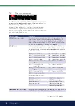
Faults can occur in the cooling unit if the ground loop has not been installed
correctly, if it has not been bled sufficiently, if it contains too little antifreeze or
is not designed to an adequate size. Poor or insufficient circulation can result
in the heat pump triggering an alarm in the case of low evaporation. If the
temperature difference between the ingoing and outgoing temperature is too
large, the product triggers an alarm and “Low brine flow” is displayed. The
probable cause is that there is still air in the brine circuit. Bleed thoroughly,
which may in some cases take up to a day. Also check the ground loop. See
also the section entitled “Connecting the brine system”.
Check:
• that the brine pump speed value is not set too low. Try to increase this
if a problem arises.
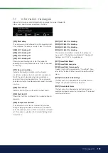
Reset the “Low evaporation” alarm on the display. Where a malfunction
repeatedly occurs, call in a technician to investigate and rectify the fault.
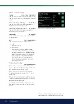
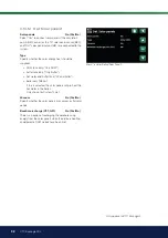
If the text “Low brine temp” is displayed, the ground loop may not be
large enough or there may be a fault with the sensor. Check the brine
circuit temperature in the “Current operation data” menu. If the incoming
temperature falls below -5 °C during operation, call in a technician to inspect
the brine circuit.
Motor protection
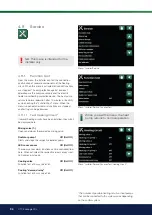
CTC EcoLogic constantly monitors the compressor’s operating current and
an alarm is triggered if the compressor is drawing an unusually high current.
When a fault occurs, the message “Motor protect high current” is displayed.
The cause of the fault may be as follows:
• Phase failure or mains interruption. Check the fuses, which are the
most common cause.
• Compressor overload. Call out a service engineer.
• Faulty compressor. Call out a service engineer.
• Circulation too poor between the cooling circuit and cylinder. Check
the heat medium pump (charge pump).
• Abnormally high temperature in the brine circuit. Call out a service
engineer.
If the heat is not even, check:
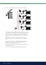
• That the placement of the room sensors is appropriate for the house.
• That the radiator thermostats don’t interfere with the room sensor.
• That no other heat sources/cold sources interfere with the room
sensor.
• That the mixing valve is not in the manual position.
Summary of Contents for EcoLogic L
Page 2: ......
Page 3: ...162 505 61 2 2021 02 25 Installation and Maintenance Manual CTC EcoLogic L M ...
Page 136: ...136 CTC EcoLogic M L 9 Valves ...
Page 160: ......
Page 161: ......
Page 162: ......
Page 163: ......

