5 - 7
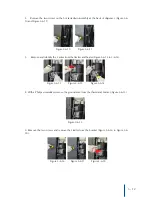
5. If required, cut the ties holding the wires together, taking care not to damage any of the wires (Figure
5-4-7).
6. Remove the 2 screws from the sensor bracket on the hot tank (Figure 5-4-8 and Figure 5-4-9).
7. There is enough heat transfer paste on the tank and old sensor to simply wipe the face of the new
sensor against the old one (Figure 5-4-10). Place into position and evenly tighten the two screws (torque to
3.4-6.9 lbf.in) (Figure 5-4-11 and Figure 5-4-12).
8. Connect the terminal for the hot sensor to the PCB (take care to ensure proper installation location) (
Figure 5-4-13).
9. Reinstall PCB Cover over PCB (Figure 5-4-14), taking care not to pinch any wires .
Figure 5-4-7
Figure 5-4-8 Figure 5-4-9
Figure 5-4-10 Figure 5-4-11 Figure 5-4-12
Figure 5-4-13
Figure 5-4-14


