5 - 3
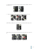
5. Remove the protective cover from the PCB, and disconnect the cold sensor terminal from the
PCB. (Figure 5-2-5 and Figure 5-2-6).
6. If required, cut the ties holding the wires together, taking care not to damage any of the wires
(Figure 5-2-7).
7. Pull the sensor tube out from the Evaporator Insulation to remove (Figure 5-2-8).
8. Install the replacement Cold Sensor into the Evaporator Insulation (insertion length approxi-
mately 5 inches/125mm) (Figure 5-2-9 and Figure 5-2-10).
Note: Care should be taken while installing the cold sensor that the end within the evaporator insu-
lation is in the proper position.
Figure 5-2-7
Figure 5-2-8
Figure 5-2-9 Figure 5-2-10
Figure 5-2-5 Figure 5-2-6


