4 - 7
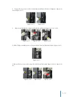
3. With all the screws removed, remove the protective cover from the PCB (Figure
4-5-10 ), and disconnect the cold sensor terminal from the PCB (Figure 4-5-11).
pull the front panel near the base plate forward to remove (Figure 4-5-12 and Figure 4-5-
13).
4. For reassembly align the bottom of the front panel with the appropriate guides in the
base plate (Figure 4-5-14). Then follow the above steps in reverse order.
Figure 4-5-10 Figure 4-5-11 Figure 4-5-12 Figure 4-5-13
Figure 4-5-14


