5 - 5
SECTION 5: Electrical Component
Diagnosis and Replacement
1.
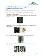
Remove Bottle and open the Top Cover (Figure 5-3-1 and Figure 5-3-2)
2.
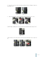
Remove screw from the PCB access cover (Figure 5-3-3) and remove the cover (Figure
5-3-4 and Figure 5-3-5)
3.
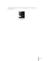
Behind the access cover are 3 switches: (Factory Setting highlight in Blue)
Allow the cooler to stabilize for 2-3 hours to ensure the proper temperature of the cold water.
Figure 5-3-3 Figure 5-3-4 Figure 5-3-5
Water Temperature Adjustment
Notice:
The information and/or procedures presented in the following demonstration(s) should be performed by a trained Water Cooler
Service Technician only.
Never attempt to service or repair a water cooler while it is plugged into any power supply.
Prior to any service or repair of the water cooler, ensure that the water has been completely drained from the system.
Figure 5-3-1 Figure 5-3-2
Switch
Top (Cold Water)
Middle (Hot Water)
Bottom (CrystalFlo™ Timer)
Left Position
Coldest 41°F / 5°C
Hottest 187°F / 86°C
12 Month Timer
Middle Position
46°F / 8°C
183°F / 84°C
6 Month Timer
Right Position
50°F / 10°C
179°F / 82°C
OFF


