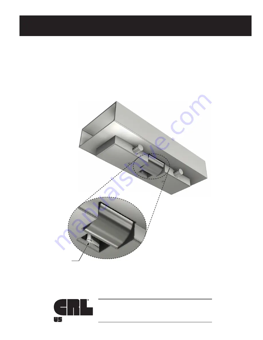
background image

11M0255

INSTALLATION INSTRUCTIONS

CRL ESK1/ESP1

ELECTRIC STRIKE KEEPER 

FOR SINGLE DOORS

ALUMINUM

Phone: (800) 421-6144 • Fax: (800) 587-7501

crlaurence.com • usalum.com • crl-arch.com

NOTE: 

Sensor feature 


available on ESP


Strikes only.


Summary of Contents for ESK1

Page 1: ...TALLATION INSTRUCTIONS CRL ESK1 ESP1 ELECTRIC STRIKE KEEPER FOR SINGLE DOORS ALUMINUM Phone 800 421 6144 Fax 800 587 7501 crlaurence com usalum com crl arch com NOTE Sensor feature available on ESP St...

Page 2: ...ON 08 11 VOLTAGE AND WIRING 08 ELECTRIC STRIKE ATTACHMENT 09 ELECTRIC STRIKE ADJUSTMENT 10 RE ATTACH STRIKE COVER AND MAKE FINAL ADJUSTMENTS 11 The rapidly changing technology within the architectural...

Page 3: ...i A156 3 Exit Devices iii A156 18 Materials and Finishes b Americans with Disabilities Act A D A c American Society for Testing and Materials ASTM d National Fire Protection Association NFPA 101 e Und...

Page 4: ...1 SHCS Stop Screw for Glass Mount Doors Bumper Sold Separately 2 BMPRBR Rubber Bumper for Strike D E FASTENERS AND PARTS LIST CALL OUT QTY FASTENER FASTENER DESCRIPTION PART USED WITH PART NUMBER 2 5...

Page 5: ...TACHED TEMPLATE INTERIOR FIG 1 Drill and Tap 5 16 18 x 3 4 UNC 2 Places Centerline of Pivot 4 1 8 104 8 to Leading Edge Swing 3 This Side 4 1 8 104 8 to Leading Edge Swing 4 This Side 1 25 4 on 1 2 12...

Page 6: ...m NOT TO SCALE HEADER PREPARATION CONTINUED Interior Edge of Header Use Template from Box Drill and Tap for a 2 5 16 18 x 3 4 SHCS REINSTALL THE PREPARED HEADER AND CONTINUE WITH THE ELECTRIC STRIKE I...

Page 7: ...p 2 F O G DIRECT TO GLASS MOUNTING FIG 5 Header FIG 6 NOTE Face of the Strike Keeper MUST be set at 87 degrees as illustrated in Figure 6 To adjust the Strike refer to page 10 Electric Wires Header Fa...

Page 8: ...Before installing the strike make the necessary wire connections Refer to the table below in Fig 7 for ESK ESP strikes for latch deadbolt and monitor on ESP strikes only 2 When you are installing the...

Page 9: ...SHCS A ELECTRIC STRIKE ATTACHMENT CONTINUED 1 Fasten the Electric Strike to the header using 2 5 16 18 x 3 4 SHCS Fig 8 2 Check the horizontal alignment Make sure that the centerline of the latch bol...

Page 10: ...12 F Push and hold the Strike Keeper in against the Jig and re tighten the 2 1 4 20 x 1 2 SHCS Fig 13 G Remove the ESP040 Electric Offset Jig Fig 14 H Install the Electric Strike Assembly using the 2...

Page 11: ...against the rubber stop pads the retractable bolt should automatically move upward to engage the Strike 3 If it does NOT engage the door stops should be adjusted inward Do not overtighten This can cau...

Reviews: