CRL ESK1/ESP1 - ELECTRIC STRIKE KEEPER FOR SINGLE DOORS
08
crlaurence.com | usalum.com
NOT TO SCALE
ELECTRICAL RATINGS FOR
SOLENOID
CONTINUOUS DUTY
24V DC
RESISTANCE IN OHMS
96
AMPS
.25
MINIMUM GAGE
REQUIREMENTS
300 FEET OR LESS
18
ga.
300 - 400 FEET
16
ga.
WIRE STANDARDS
WIRE #
COLOR
USAGE
1
BLACK
RETURN (–)
2
PURPLE
24V DC POWER
3
BLACK
COM
4
RED
NO
5
BLUE
NC
ELECTRIC
STRIKE
BOLT
MONITOR
SWITCH
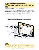
FIG. 7
Strike
Mechanism
Sensor
Purple Wire
Black Wire
Red Wire
Black Wire
Blue Wire
VOLTAGE AND WIRING
ELECTRIC STRIKE ATTACHMENT
1. Before installing the strike, make the necessary wire connections.
Refer to the table below in.
(Fig. 7)
for ESK/ESP strikes.
for latch/deadbolt and monitor on ESP strikes only.
2. When you are installing the strike into the frame cut-out (Fig. 3, page 06), tuck the
wiring away from the strike area to avoid pinching.
NOTE:
Proper operating voltage must be supplied to the Strike for it to function
correctly. Voltage must be 10% of the required voltage that is
listed on the Strike Label.
6A
6B
Specifications
• Handle material: 1-1/4" (32) diameter Stainless Steel Tubing.
• Switch, SPDT, maximum contact rating 5 Amps @ 250 Volts.
• Watertight precision body.
• 10 million cycle mechanism.
• Meets with IP67 (IEC 529) requirements.
2
4
5
1
3
6A
6B