CRESTRON
Operations Guide - DOC. 8108B
Series 3500 Touchpanels
••
9
Hardware Hookup
Due to configuration differences, the hookup diagram differs for each Series 3500
touchpanel. As a result, there are different connection views for the lectern-mount
and adjustable tiltcase configurations. Complete the following steps in the order
provided to ensure proper installation of the unit.
1. Before making any connections, review latest revision of network
interconnection drawing (Doc. 5411) or, if necessary, the network
modular cable requirements (Doc. 5682).
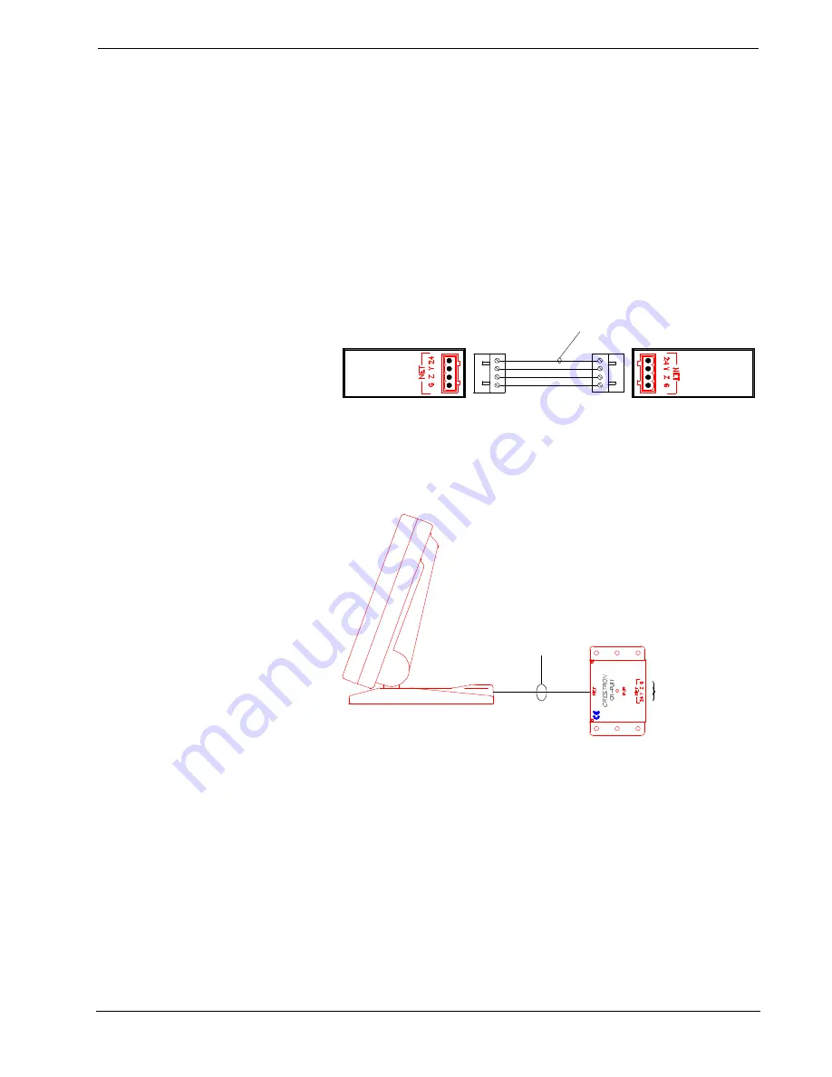
2. Connect the touchpanel to the CRESNET II network via a CRESNET
II network cable, shown below, and appropriate interface module.
Recommended CRESNET II Network Cable, Part No. CRE-2S18218
CN-RJ11,
VT-3500IMC,
CT-3500L,
& VT-3500L
CNRACK OR
CNRACK-D
OR CNMS
NOTE:
Wire is available from Liberty
Wire & Cable (719) 260-0061.
#18 AWG Stranded Wire
2x Twisted Pairs
•
A supplied cable assembly (P/N 15717) with 6-position, 6-pin
connectors on each end connects the CT-3500 to the CN-RJ11, shown
below. Connect the CN-RJ11 to the CRESNET II system via the
network cable.
CT-3500 Typical Connection Diagram
CONNECT TO CNMS,
CNRACK, OR CNRACK-D
Refer to the CRESNET II
Network Cable drawing in
this section of the Guide.
SIDE VIEW OF CT-3500
NOTE:
UNITS IN THIS ILLUSTRATION
ARE NOT DRAWN TO SCALE.
CABLE ASSEMBLY
(P/N 15717)
•
A supplied 11 to 12 foot network cable assembly (P/N 15709) with 8-
position, 8-pin connectors on each end connects the VT-3500 to the
VT-3500IMC, shown after this paragraph. Connect the CN-RJ11 to
the CRESNET II system via the network cable.


