background image

20

Crazy3DPrint  CZ-300 

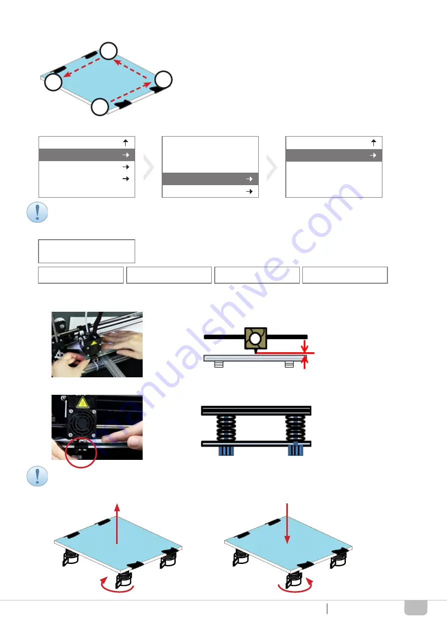
(2) The calibration should measure four points as below illustration.

(3) Select “Prepare”, “Level bed”, and then “Level bed” and press the knob.

(4) Calibrate the print bed one point by one point; that comes with a “BEEP” sound after completion at each step.

4.1) Insert the paper between the nozzle tip and the glass surface at each step; where the paper shall pass through
       the gap smoothly.

4.2) Adjust the plastic setscrew under the print bed to make the print bed to horizon position if needed.

4.3) Turn the setscrew clockwise direction, the print bed is moving up; oppositely, the print bed is moving down.

PRINT BED CALIBRATION

1

2

3

4

Info Screen

Prepare

Control
Print from SD
Change SD card

Auto home

Cancel

Set home offsets
Set Origin

Level Bed

Level Bed

Move axis

The operation of controlling the panel can refer to the section of LCD PANEL CONTROL. 

Users may use a tool to prevent the metal setscrew from spinning while doing the adjustment.

Click to Begin

Next Point:    

1/4

Next Point:    

2/4

Next Point:    

3/4

Next Point:    

4/4

Summary of Contents for CZ-300

Page 1: ...CZ 300 USER MANUAL Version 1 2 from January 2019 Crazy3DPrint Group ENGLISH Please always refer to the updated version of CZ 300 user manual https www crazy3dprint com support...

Page 2: ...4 CZ 300 APPEARANCE 5 SPECIFICATIONS 5 UNPACKING AND INSTALLATION 6 UNBOXING 6 ACCESSORY CHECKLIST 6 INSTALLATION 7 OPERATION 16 LCD PANEL CONTROL 16 PRINT BED CALIBRATION 19 SOFTWARE SETTINGS 21 FIRS...

Page 3: ...rmanent damage to the printer Never place any liquid containing items on top of the device or power supply If any liquid spills into the unit fire or electric shock may result The device may generate...

Page 4: ...the AC input at either 110 or 220 volts depending on the region area s voltage There is a risk of burns from touching the heated up device unit during the printing process This is because the nozzle t...

Page 5: ...hat offers rapid and cost effective prototyping The CZ 300 is an easy to use 3D printer designed with simple frame structure that separates in two parts upper and lower frames for you to start with Yo...

Page 6: ...WxDxH Layer Resolution Filament Diameter Operating Temperature Nozzle Temperature Supported File Type Storage Temperature Filament Print Bed Operating System s User Interface Transmission Gross Weight...

Page 7: ...following cut the pp strap off Lifting up the set of printer gently to prevent intentional damage of the device and loss of the accessories Also be careful the print bed glass and avoid to damage as w...

Page 8: ...M4x8 4 3 2 4 5 4 7 3 5 7 3 7 6 13 3 8 INSTALLATION NO NO NO 1 2 3 1 4 2 5 13 1 8 4 1 1 1 1 7 3 8 1 11 1 6 3 2 4 3 1 1 1 9 3 3 4 4 2 1 1 10 3 4 4 5 2 1 1 11 3 5 4 6 14 1 1 12 3 6 4 7 2 1 1 13 3 7 5 4 1...

Page 9: ...ews and nuts Users may take out the end cap in case difficult of inserting nuts to the groove Also do not fully tighten all screws and nuts first and keep the metal plate freely moving Users may use t...

Page 10: ...lowing install two screws M4x30 into the bottom of the lower frame for both sides and lock up tightly by using a screwdriver Be careful the print bed glass and avoid to damage as well as get hurt All...

Page 11: ...e height of extruder motor should be parallel to the upper frame end avoiding collision to the release arm when Z shaft rising Users may use hand hardly press the end cap into the upper frame 1 Insert...

Page 12: ...printer parts can be referred to the names in the table of CZ 300 APPEARANCE Please hold the end of cable near the control box to prevent unintentional pulling of the device causing any electrical da...

Page 13: ...s Motor 6PIN Black Housing C Extruder Motor 6PIN Blue Housing D Z Axis Motor 6PIN White Housing Z Axis Sensor 3PIN White Housing X Axis Sensor 3PIN Black Housing A Y Axis Motor 6PIN Yellow Housing B Y...

Page 14: ...motor socket following plug the 3 pin yellowing housing into the Y sensor socket The cable should be placed underneath the lower frame to prevent accidental pulling by the rod and the print bed while...

Page 15: ...groove following tie up cable ties and cut them to a proper length INSTALLATION SECURING PRINT BED CABLE 1 Take out the platform clip following install the cable with it and clip back to the print be...

Page 16: ...can be left right moving freely while printing It is suggested that the filament spool should maintain 2 fingers interval to the upper frame Accessory Preparation Power Cord Control Box Power Supply...

Page 17: ...Move axis Disable steppers Preheat PLA Preheat ABS Cooldown Main Control Temperature Prepare Autotemp On Prepare ABS Bed Preheat PLA conf Preheat ABS conf No SD card Print from SD Init SD card Change...

Page 18: ...to Init SD card and press the knob 2 Select Info Screen and press the knob to be back to the main menu 3 Select Change SD card to change another SD card if needed by following the same steps 2 Knob co...

Page 19: ...ss the knob to adjust print head X Y axis movement 3 Turn the knob to Move X and press the knob after setting 4 Turn the knob to Move Y and press the knob after setting Prepare Move 10mm Move 1mm Move...

Page 20: ...pre heating when using PLA filament 3 Select Preheat ABS conf and press the knob for pre heating when using ABS filament Main Control Temperature Nozzle 210 210 240 000 10 70 Bed Preheat PLA conf Auto...

Page 21: ...lastic setscrew under the print bed to make the print bed to horizon position if needed 4 3 Turn the setscrew clockwise direction the print bed is moving up oppositely the print bed is moving down PRI...

Page 22: ...tup exe for users easily setting up the parameters in terms of printer dimensions extruder details and other specific commands Users can find the profile from Software Folder in the SD Memory Card or...

Page 23: ...D card to the slot following select Print from SD and choose the file 1 Prepare the USB cable4 1 to connect the control box with your laptop or computer following open the file with software generated...

Page 24: ...and select Update driver 2 Select Browse my computer for driver software following browse a suitable driver file for the version of your Windows 3 Close the window as below after completing the updat...

Page 25: ...following the steps below Always keep the print bed glass clean there might be excess glue or left plastic from previous prints stuck to the sur face This can cause a warped or uneven print surface t...

Page 26: ...to abnormal after reaching the designated temperature Print bed Raising Temperature Abnormal 1 Abnormally slow during raising temperature lessthan 2 degrees C within 60secs 2 Temperature suddenly chan...

Reviews: