


To maintain efficient grinder pump operation, care should
be taken to keep both the radial cutter (4) and shredding
ring (16) cutting edges sharp. Neither part can be
sharpened to renew the cutting ability. The radial cutter (4)
must be replaced and the shredding ring either reversed
or replaced.
E-1.2) Reassembly:
To replace impeller (14) on shaft, turn clockwise while
holding shaft stationary with a screwdriver. Next install
shredding ring (16) by pressing into body (19) with the use
of an arbor press.
NOTE:
It is important that the grooves
in the shredding ring are at the top of the pump and the
solid part is to the bottom. This is to keep some solids from
setting in the grooves and causing a jam at start up. Then
insert throat (17) into body (19) with three flat head allen
screws (18). Apply a thin coat of petroleum jelly to the
square ring (20) and place on body (19). Place motor
assembly on body (19), being careful not to damage
square rings (20). Place washers (9) and nuts (21) on studs
(22) and tighten. Screw radial cutter (4) on shaft clockwise.
Hold motor shaft stationary with screwdriver and tighten.
Then replace washer (5) and screw (6). Radial cutter (4)
to be flush with shredding ring (16) on suction side to within
±
.020.
E-2) SHAFT SEAL SERVICE:
CAUTION ! - Handle seal parts with extreme
care. DO NOT scratch or mar lapped surfaces.
E-2.1) Disassembly and Inspection:
Seal-
To expose shaft seal (12) for examination
disassemble volute, cutter and impeller as outlined in
paragraph E-1.1.
To inspect seal further, remove retaining ring (12d), spring
(12c) and rotating member (12b) from shaft (see Fig. 3).
Examine all seal parts and especially contact faces.
Inspect seal for signs of wear such as uneven wear pattern
on stationary members, chips and scratches on either seal
face.
DO NOT
interchange seal components, replace the
entire shaft seal (12). If replacing seal, remove stationary
(12a) by prying out with flat screw driver.
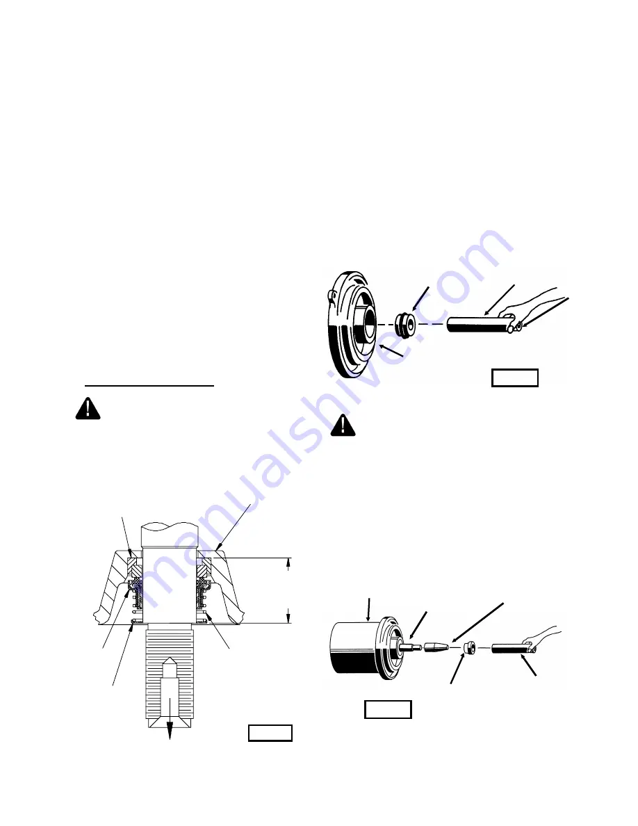
E-2.2) Reassembly:
Seal-
Clean and oil seal cavity in seal plate (10). Lightly oil
(
DO NOT
use grease) outer surface of stationary member
(12a). Press stationary member (12a) firmly into seal plate
(10), using a seal pusher (see parts list- seal tool kit).
Nothing but the seal pusher is to come in contact with seal
face (see Fig. 4).
IMPORTANT ! - DO NOT HAMMER ON THE
SEAL PUSHER- IT WILL DAMAGE THE SEAL
FACE.
Make sure the stationary member is in straight. Slide a
bullet (see parts list-seal tool kit) over motor shaft. Lightly
oil (
DO NOT
use grease) shaft, bullet and inner surface of
bellows on rotating member (12b) (see Fig. 5). With lapped
surface of rotating member (12b) facing inward toward
stationary member (12a), slide rotating member (12b) over
bullet and onto shaft, using seal pusher, until lapped faces
of (12a) and (12b) are together (see Fig. 3).
PUMP END
(OUTBOARD END)
SEAL
ASSEMBLY
(12)
Seal Plate (10)
Fig. 3
MOTOR END
(INBOARD END)
Stationary (12a)
Rotating
Member
(12b)
Retaining Ring
(12d)
Spring (12c)
Seal Plate (10)
SEAL PUSHER
Stationary Member (12a)
Polished Face Out.
Fig. 4
MOTOR & SEAL
PLATE
STATIONARY
(12a)
BULLET
ROTATING
MEMBER
(12b)
SEAL PUSHER
Fig. 5
8


