background image

9

FIGURE 2

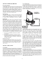
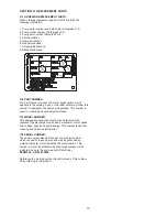
SECTION E: PREVENTATIVE MAINTENANCE

As the motor is oil fi lled, no lubrication or other maintenance 
is required, and generally Barnes Pumps will give very 
reliable service and can be expected to operate for years on 
normal sewage pumping without failing. However as with any 
mechanical piece of equipment a preventive maintenance 
program is recommended and suggested to include the 
following checks:

1)   Inspect motor chamber for oil level and contamination
 

and repair as required per section F-1.

2)  Inspect impeller and body for excessive build-up or
 

clogging and repair as required per section F-2.

3)  Inspect motor and bearings and replace as required 
 

per section F-3.

4)  Inspect seal for wear or leakage and repair as required
 

per section F-4.

SECTION F: SERVICE AND REPAIR

NOTE:

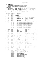
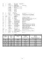
 All item numbers in ( ) refer to Figures 15 thru 18.

F-1) Lubrication:

Anytime the pump is removed from operation, the cooling oil 
in the motor housing (6) should be checked visually for oil 
level and contamination.

F-1.1) Checking Oil:
Motor  Housing-

 To  check  oil,  set  unit  upright.  Remove  pipe 

plug  (39)  from  motor  housing  (6).  With 

a  fl ashlight,  visually 

inspect  the  oil  in  the  motor  housing  (6)  to  make  sure  it  is 
clean and clear, light amber in color and free from suspended 
particles.  Milky  white  oil  indicates  the  presence  of  water.  Oil 
level should be just above the motor when pump is in vertical 
position.

F-1.2) Testing Oil:
1.) 

Place pump on it’s side, remove pipe plug (39), from


motor housing (6) and drain oil into a clean, dry container.

2.)

  Check oil for contamination using an oil tester with a


range to 30 Kilovolts breakdown.

3.) 

If oil is found to be clean and uncontaminated


(measuring above 15 KV. breakdown), refi ll the motor


housing as per section F-1.4.

4.) 

If oil is found to be dirty or contaminated (or measures


below 15 KV. breakdown), the pump must be 


carefully inspected for leaks at the shaft seal (28), cord


assemblies (16) and (56 if used), square ring (27) and 


pipe plug (39), before refi lling with oil. To locate the 


leak, perform a pressure test as per section F-1.3.


After leak is repaired, dispose of old oil properly, and 


refi ll with new oil as per section F-1.4.

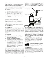
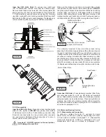
F-1.3)  Pressure Test:
Pumps  that  have  been  disassembled,  Motor  Housing  -

  If 

the  pump  has  been  disassembled,  the  oil  should  be  drained 
before a pressure test, as described in section F-1.1. Remove 
pipe  plug  (39)  from  motor  housing  (6). Apply  pipe  sealant  to 
pressure  gauge  assembly  and  tighten  into  hole  (See  Figure 
2).    Pressurize  motor  housing  to  10  P.S.I.  Use  soap  solution 
around  the  sealed  areas  and  inspect  joints  for  “air  bubbles”.

If,  after  fi ve  minutes,  the  pressure  is  still  holding  constant, 
and  no  “bubbles”  are  observed,  slowly  bleed  the  pressure 
and remove the gauge assembly. Replace oil as described in 
section F-1.4. If the pressure does not hold, then the leak must 
be located and repaired.

Pumps that have NOT been disassembled, Motor Housing- 

The pressure test may be done with the oil at its normal level.  
Remove  pipe  plug  (39)  from  motor  housing  (6).  Apply  pipe 
sealant  to  pressure  gauge  assembly  and  tighten  into  hole 
(See  Figure  2).  Pressurize  motor  housing  to  10  P.S.I.  Use 
soap solution around the sealed areas above the oil level and 
inspect joints for “air bubbles”. For sealed areas below the oil 
level,  leaks  will  seep  oil.  If,  after  fi ve  minutes,  the  pressure 
is  still  holding  constant,  and  no  “bubbles”/oil  seepage  is 
observed,  slowly  bleed  the  pressure  and  remove  the  gauge 
assembly. If the pressure does not hold, then the leak must be 
located and repaired.

Seal Chamber (DS Units Only)-

 Set unit on its side with 

fi ll plug (44) downward, remove plug (44) and drain all oil 
from seal chamber. Apply pipe sealant to pressure gauge 
assembly and tighten into hole in outer seal plate (29). 
Pressurize seal chamber to 10 P.S.I. and check for leaks as 
outlined above.

CAUTION ! Pressure builds up extremely 
fast, increase pressure by “tapping” air 
nozzle. Too much pressure will damage 
seal. DO NOT exceed 10 P.S.I.

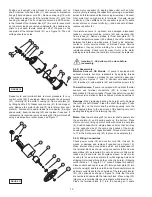
F-1.4)  Replacing Oil:
Motor Housing- 

Set unit upright and refi ll with new cooling 

oil as per Table 1 (see parts list for amount). Fill to just above 
motor as an air space must remain in the top of the motor 
housing to compensate for oil expansion (see Fig. 15 or 17). 
Apply pipe thread compound to threads of pipe plug (39) then 
assemble to motor housing (6).

Summary of Contents for 104189

Page 1: ...provement program product changes may occur As such Crane Pumps Systems reserves the right to change product without prior written notification 420 Third Street 83 West Drive Bramton Piqua Ohio 45356 Ontario Canada L6T 2J6 Phone 937 778 8947 Phone 905 457 6223 Fax 937 773 7157 Fax 905 457 2650 www cranepumps com Form No 115941 Rev N Series 2SEV 3SEV L DS 1 5 2 HP 3450 RPM 60 Hz Single and Double S...

Page 2: ...Fig 16 18 DOUBLE SEAL CROSS SECTION Fig 17 19 DOUBLE SEAL EXPLODED VIEW Fig 18 20 PARTS LIST 21 22 RETURNED GOODS POLICY 23 WARRANT START UP REPORT WARRANTY REGISTRATION SPECIAL TOOLS AND EQUIPMENT INSULATION TESTER MEGGER DIELECTRIC TESTER SEAL TOOL KIT see parts list PRESSURE GAUGE KIT see parts list Other brand and product names are trademarks or registered trademarks of their respective holder...

Page 3: ...ert fingers in pump with power connected Always wear eye protection when working on pumps Make sure lifting handles are securely fastened each time before lifting DO NOT operate pump without safety devices in place Always replace safety devices that have been removed during service or repair Secure the pump in its operating position so it can not tip over fall or slide DO NOT exceed manufacturers ...

Page 4: ...PT 30 Ft 9 1m Cord Quick connect Custom molded for sealing and strain relief SPEED 3450 RPM 60Hz nominal UPPER BEARING Design Single Row Ball Oil Lubricated Load Radial LOWER BEARING Design Single Row Ball Oil Lubricated Load Radial Thrust MOTOR Design NEMA L Single phase NEMA B Three Phase Torque Curve Oil Filled Squirrel Cage Induction Insulation Class B Class F on selected models SINGLE PHASE P...

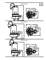
Page 5: ...5 inches mm 2SEV DS Series 3SEV L Series 3SEV DS Series ...

Page 6: ...tion or basin shall be vented in accordance with local plumbing codes This pump is designed to pump sewage effluent or other nonexplosive or noncorrosive wastewater and shall NOT be installed in locations classified as hazardous in accordance with the National Electrical Code NEC ANSI NFPA 70 or the Canadian Electrical Code CEC Never install the pump in a trench ditch or hole with a dirt bottom th...

Page 7: ...sent It is recommended that this detector be connected in series to an alarm device or the motor started coil to alert the operator that a moisture detect has occurred In the event of a moisture detect check the individual moisture sensor probe leads for continuity resistance no moisture and the junction box control box for moisture content The above situations may induce a false signal in the moi...

Page 8: ...5 480 3 60 3450 F B 4 9 13 5 14 4 SOW 0 60 15 2 17 0 3SEV1552L 1 5 600 3 60 3450 F B 3 9 11 0 14 4 SOW 0 60 15 2 22 2 3SEV2022L 2 0 240 1 60 3450 C B 16 0 42 0 12 3 SOW 0 61 15 5 1 26 55 34 3SEV2092L 2 0 200 240 3 60 3450 J B 13 2 12 30 0 14 4 SOW 0 60 15 2 3 08 3SEV2042L 2 0 480 3 60 3450 J B 6 0 15 0 14 4 SOW 0 60 15 2 12 30 3SEV2052L 2 0 600 3 60 3450 J B 4 8 12 0 14 4 SOW 0 60 15 2 19 70 3SEV1...

Page 9: ... 1 3 After leak is repaired dispose of old oil properly and refill with new oil as per section F 1 4 F 1 3 Pressure Test Pumps that have been disassembled Motor Housing If the pump has been disassembled the oil should be drained before a pressure test as described in section F 1 1 Remove pipe plug 39 from motor housing 6 Apply pipe sealant to pressure gauge assembly and tighten into hole See Figur...

Page 10: ...assembly To install impeller 33 clean the threads with thread locking compound cleaner Apply removable Loctite 603 or equivalent to shaft threads Screw impeller onto the shaft hand tight while using a screwdriver in the slot at the end of the shaft to hold it stationary Apply thread locking compound 57 to shaft threads then install jam nut 66 and torque to 40 ft lbs It is important that the spring...

Page 11: ...s of 28a and 28b are together see Figure 8 It is extremely important to keep seal faces clean during assembly Dirt particles lodged between these faces will cause the seal to leak Place spring 28c over shaft and in place on rotating member 28b making sure it is seated on retainer and not cocked or resting on bellows tail Slide retaining ring 28d over shaft and let rest on spring 28c Replace snap r...

Page 12: ...y F 4 2 Reassembly Moisture Sensors DS Models If pump is equipped with optional moisture sensors reassemble by applying thread compound to threads on probes 4 and install in upper seal plate 5 see Figures 17 and 18 Connect wire assemblies 53 to probes 4 with washers 46 and machine screws 45 Thermal Sensors If pump is equipped with optional thermal sensors use terminal connectors 52 to connect wire...

Page 13: ...ower Control Cord Refill the cooling oil as outlined in paragraph F 1 3 Make wire connections as outlined in paragraph F 4 3 Insert female end of cord plug into housing bore aligning timing mark with hole in terminal block 21 see Figure 13 Compress cord plug with compression flange 16a by tightening hex bolts 11 into the housing 6 Torque to 132 in lbs FIGURE 12 FIGURE 14 SINGLE PHASE 240 VOLT AC PS...

Page 14: ...14 FIGURE 14 CONTIUED ...

Page 15: ...the design configuration This number is used for ordering and obtaining information G 3 MODEL NUMBER This designation consists of numbers and letters which represent the discharge size series horsepower motor phase and voltage speed and pump design This number is used for ordering and obtaining information G 4 SERIAL NUMBER The serial number block will consist of a six digit number which is specific...

Page 16: ... cutter for freedom of operation security and condition Clean cutter and inlet of any obstruction 9 Loosen union slightly to allow trapped air to escape Verify that turn off level of switch is set so that the suction is always flooded Clean vent hole 10 Remove examine for damage Replace pump stator if required 11 Repair fixtures as required to eliminate leakage 12 Check pump temperature limits flu...

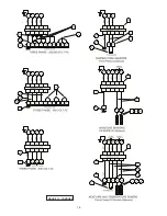
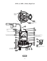
Page 17: ...17 FIGURE 15 2SEV L 3SEV L Series Single Seal ...

Page 18: ...18 FIGURE 16 2SEV L 3SEV L Series Single Seal ...

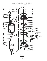
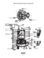
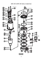
Page 19: ...19 FIGURE 17 2SEV DS 3SEV DS Series Double Seal ...

Page 20: ...20 FIGURE 18 2SEV DS 3SEV DS Series Double Seal ...

Page 21: ... 9 1 036391 Capacitor 1 Phase 10 1 039858 Capacitor Bracket 1 Phase 11 4 1 129 1 Hex Hd Cap Screw Std 5 16 18 x 75 Lg Stainless 6 1 129 1 Hex Hd Cap Screw Optional for moisture and temp sensors 12 8 026322 Lockwasher Std 5 16 Stainless 10 026322 Lockwasher Optional for moisture and temp sensors 13 1 103503 Handle 16 1 See Table 2 Power Cord Set 19 1 105197 Snap Ring Std 2 105197 Snap Ring Optional...

Page 22: ...embly 200 240V 3Ph 50 1 051621 Thermal Sensor Optional for temperature sensor Not Shown 51 2 105155 Wire Assembly Optional for temperature sensor Not Shown 52 2 625 00163 Terminal Connector Optional for temperature sensor Not Shown 53 2 105106 Wire Assembly Optional for moisture sensor 54 1 103584 Terminal Block Temperature sensor options 103585 Moisture and temp sensor options 56 1 See Table 2 Co...

Page 23: ...es between the results of eld testing conducted by or for user and laboratory tests corrected for eld performance the latter shall control RECOMMENDATIONS FOR SPECIAL APPLICATIONS OR THOSE RESULTING FROM SYSTEMS ANALYSES AND EVALUATIONS WE CONDUCT WILL BE BASED ON OUR BEST AVAILABLE EXPERIENCE AND PUBLISHED INDUSTRY INFORMATION SUCH RECOMMENDATIONS DO NOT CONSTITUTE A WARRANTY OF SATISFACTORY PERF...

Page 24: ...ent To Insure That Employees Will Not Be Exposed To Health Hazards In Handling Said Material All Applicable Laws And Regulations Shall Apply IMPORTANT WARRANTY REGISTRATION Your product is covered by the enclosed Warranty To complete the Warranty Registration Form go to http www cranepumps com ProductRegistration If you have a claim under the provision of the warranty contact your local Crane Pump...

Reviews: