4
DISCHARGE ..................
2” NPT, Vertical, Bolt-on Flange
3” NPT, Vertical, Bolt-on Flange
LIQUID TEMPERATURE
104°F (40°C) Intermittent
MOTOR HOUSING ........
Cast Iron ASTM A-48, Class 30
VOLUTE .........................
Cast Iron ASTM A-48, Class 30
SEAL PLATE .................
Cast Iron ASTM A-48, Class 30
IMPELLER
Design
...........
Vortex, Open with Pump out vanes
on Back side. Dynamically
balanced, ISO G6.3
Material
........
85-5-5-5 Bronze
SHAFT ............................
416 Stainless Steel
SQUARE RINGS ............
Buna-N
HARDWARE ..................
300 Series Stainless Steel
PAINT .............................
Air dry enamel, top coat
SEAL
Design
..........
Single Mechanical, or Tandem
Mechanical with oil fi lled reservoir
Material
........
Rotating Faces - Carbon
Stationary Faces - Ceramic
Elastomer - Buna-N
Hardware - 300 series stainless steel
CORD ENTRY ................
2” NPT - 20 Ft. (6.1m)
3” NPT - 30 Ft. (9.1m) Cord, Quick
connect. Custom molded for sealing
and strain relief
SPEED ...........................
3450 RPM, 60Hz (nominal)
UPPER BEARING:
Design
..........
Single Row, Ball, Oil Lubricated
Load
.............
Radial
LOWER BEARING:
Design
..........
Single Row, Ball, Oil Lubricated
Load
.............
Radial & Thrust
MOTOR:
Design
..........
NEMA L, Single phase,
NEMA B, Three Phase Torque Curve,
Oil Filled, Squirrel Cage Induction
Insulation
......
Class B
Class F on selected models
SINGLE PHASE .............
Permanent Split Capacitor (PSC)
Includes overload protection in motor
THREE PHASE ..............
200-240/480 is Tri voltage motor.
600V. Requires overload protection
to be included in control panel
OPTIONAL EQUIPMENT:
Seal Material, Impeller Trims, Additional Cord,
N/C Temperature Sensors with cord for 3 Phase pumps
(Requires relay in Control Panel). N/O Moisture Sensor with
cord for DS pumps (Requires relay in Control Panel), 3” NPT
Discharge Adapter
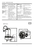
SECTION: A - PUMP SPECIFICATIONS:
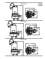
inches
(mm)
2SEV-L Series
Summary of Contents for 104189
Page 5: ...5 inches mm 2SEV DS Series 3SEV L Series 3SEV DS Series ...
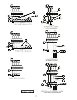
Page 14: ...14 FIGURE 14 CONTIUED ...
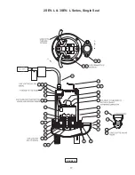
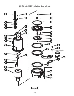
Page 17: ...17 FIGURE 15 2SEV L 3SEV L Series Single Seal ...
Page 18: ...18 FIGURE 16 2SEV L 3SEV L Series Single Seal ...
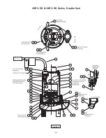
Page 19: ...19 FIGURE 17 2SEV DS 3SEV DS Series Double Seal ...
Page 20: ...20 FIGURE 18 2SEV DS 3SEV DS Series Double Seal ...


