24
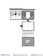
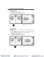
MD50W 2 Valve Manifold [FIG.24]
MD100W 4 Valve Manifold [FIG.25]
1.)
Connect Low (A) and High (B) Service hoses to
service ports (E) and (D)
1.)
Connect Low (1) and High (2) Service
hoses to service ports (L) and (H)
2.)
Connect hose from tee (C) to Inlet port of
Vacuum Pump. Use the fitting on the tee with the
valve core.
2.)
Connect 3/8” hose from port (4) to
Vacuum pump inlet port
3.)
Connect another hose from the open port of tee
(C) to the valve of a refrigerant supply tank. Supply
tank valve must be off.
3.)
Connect another hose from port (3) to
refrigerant supply tank’s valve. Supply tank
valve must remain off.
4.)
Check Low and High Side pressure readings, if zero PSIG or lower continue. If pressure reads
higher than 0 PSIG, run Refrigerant RECOVERY
5.)
Once it is determine no refrigerant is present in system, start vacuum pump.
6.)
Open low side valve (A)
6.)
Open low side valve (A)
Open high side valve (B)
7.)
Open high side valve (B)
7.)
Open valve (D). Open valve (C), but do
not open supply tank valve.
8.)
Note: A Vacuum Gauge (VG200) can be
connected via service tee to equipment to monitor
vacuum pump’s progress.
8.)
Note: Optional Vacuum Gauge Accessory
(MDXVG) can be connected via service tee
to the equipment to monitor vacuum pump’s
progress.
9.)
Evacuate system according to manufacturer’s specifications; close high and low side hand
knobs.
10.)
Disconnect Vacuum Pump hose from valved
port on Tee (C). The valve core will seal when hose is
removed, thus preserving the vacuum.
10.)
Close valve (D) once the required
vacuum level is reached. Turn off vacuum
pump.
The unit is now ready for Vacuum Leak test or High Side Charging Procedure.
EVACUATING PROCEDURES
CHARGING PROCEDURE - LOW SIDE
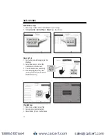
MD50W 2 Valve Manifold [FIG.24]
MD100W 4 Valve Manifold [FIG.25]
1.)
The following instructions are to add charge to a pressurized system, known as “topping off”.
2.)
Connect Low (A) and High (B) Service hoses to
service ports (E) and (D). All valves should be closed.
2.)
Connect Low (1) and High (2) Service hoses
to service ports (L) and (H)
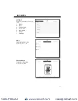
3.)
Connect a hose from the open port on tee (C) to
valve fitting on supply tank.
3.)
Connect a hose from port (3) to refrigerant
supply tank’s valve.
4.)
Open supply tank valve. For blends, turn tank upside down or make sure liquid refrigerant is being
charged.
5.)
Push valve core on tee (C) until refrigerant comes
out. This will purge the hose from the supply tank.
5.)
Open valve (C). With hose disconnect from
port (4), slightly open valve (D) until
refrigerant comes out. This will purge the hose
from the supply tank.
6.)
Turn refrigerant system on. Monitor pressure gauges. Use superheat and subcooling features to help
determine when charge amount is optimal.
7.)
Slightly open Low Side Valve (A) to allow liquid refrigerant to flow into low side of equipment. Caution
should be used when charging liquid refrigerant into low side of a refrigeration system.
8.)
Close Low Side valve (A) when desired amount of refrigerant has been added. Note the use of a scale
is required.
9.)
Let equipment temperatures and pressures stabilize. Check superheat and/or subcooling levels.
Repeat charge if necessary.
10.)
Once done, close off supply tank valve and disconnect all hoses. Use Caution as all hose connections
are under pressure.
Once charge is complete, an electronic refrigerant leak detector should be used to confirm leaks do not exist.
www.calcert.com
1.888.610.7664
0
5
10
15
20
25
30

