background image

CONNECTIONS AND SETUP 

-10- 

3.2 Camera Connection 

The cameras must be connected and power-supplied before the DVR is turned on. Connect the camera with the 

indicated power supply. And then connect the camera video output to the DVR video input port with a coaxial cable or 

RCA lines with BNC connectors (

The DVR will automatically detect the video system of the camera

). 

Note: For detailed DVR video input / output ports, please refer to “2.2 Rear Panel” at page 6. 

For detailed camera operation, please refer to its own manual. 

3.2.1 Regular Camera Connection 

1) 

Connect the camera with indicated power supply. 

2) 

Connect the camera video output to the DVR video input port with a coaxial cable and BNC connector. 

3.2.2 Speed Dome Camera Connection


The following description is taking our brand’s speed dome camera as an example. For detailed PIN / port 

connection, please refer to “APPENDIX 1 PIN CONFIGURATION” at page 64; for DVR setting to control the speed 

dome camera, please refer to “7.1.8 Remote” at page 30. 

RJ11 Line 


RS485-A: 

Red wire


RS485-B: 

Green wire


The RJ11 line is not supplied in the sales package. 


15 PIN D-Sub Connector


RS-485 Port


RS485-A: 

PIN 11


RS485-B: 

PIN 10


RS485-A: 

PIN 2


RS485-B: 

PIN 3


Solder Side of

15-pin D-Sub connector

1

9

12

13

14

15

16

17

2

3

4

5

6

7

8

10

11

RS485 -A: PIN11 / RS485-B: PIN1 0


D-Sub connector is supplied with the DVR package.


Example of RS485 port on the DVR rear panel.


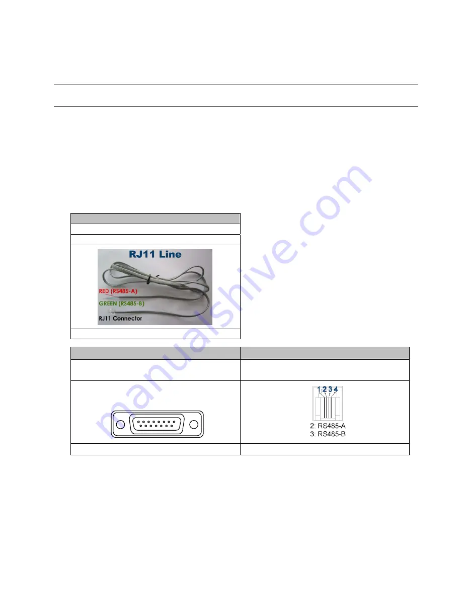
STEP 1: Get a RJ11 line with the proper length to your connection. 

Different RJ11 connector may have different wire layout, so the connection might be different. If you 

cannot control the DVR after connection, please reverse the RJ11 line connection with the DVR. 

STEP 2: Remove one end of the insulating coating of the RJ11 line. 

Remove one end of the insulating coating of the RJ11 line to find the RS485-A and the RS485-B wires, 

and remove the insulating coating to reveal the naked wires for further connection. 

STEP 3: Twist the RS485-A and RS485-B wires of the RJ11 line and the speed dome camera together. 

Twist the RS485-A (red) and RS485-B (green) wires of the RJ11 line to the RS485-A (brown) and 

Summary of Contents for CPD541D

Page 1: ...CPD541D_manual_V1 1 CPD541D H 264 Network DVR User Manual Please read instructions thoroughly before operation and retain it for future reference ...

Page 2: ...DE MPEG 4 VIDEO NO LICENSE IS GRANTED OR SHALL BE IMPLIED FOR ANY OTHER USE ADDITIONAL INFORMATION INCLUDING THAT RELATING TO PROMOTIONAL INTERNAL AND COMMERCIAL USES AND LICENSING MAY BE OBTAINED FROM MPEG LA LLC SEE HTTP WWW MPEGLA COM GPL Licensing This product contains codes which are developed by Third Party Companies and which are subject to the GNU General Public License GPL or the GNU Less...

Page 3: ... 4 Date and Time Setting 11 3 5 Password Setting 12 4 BASIC OPERATION 13 4 1 Live Page 13 4 2 Recording 13 4 3 Playback 14 4 4 Key Lock and Unlock 15 4 5 Upgrade 15 4 6 Search 15 5 MAIN MENU 16 5 1 Menu Configuration 16 5 2 Menu Operation Instruction 16 6 QUICK START MENU 17 6 1 Status 17 6 2 Manual Record 18 6 3 Timer 19 6 4 Date 20 7 ADVANCED MENU 22 7 1 Advanced Configuration 22 7 1 1 Camera 22...

Page 4: ...l Panel 38 8 1 3 General Operation 39 Record 39 Playback 39 Network Backup 40 8 1 4 Detailed Functions 41 Image Display 41 Address Book 41 Miscellaneous Control 42 Information 58 DVR Control 59 8 2 IE Web Browser 61 8 3 Quick Timer Player 63 APPENDIX 1 PIN CONFIGURATION 64 APPENDIX 2 RECORDING TIME TABLE For 4CH Model Only 67 APPENDIX 3 COMPATIBLE USB FLASH DRIVE BRAND 68 APPENDIX 4 COMPATIBLE HDD...

Page 5: ...s excellent for clear and detailed image z Intelligent Motion Trigger Recording R E T R Remote Event Trigger Recording Activates event recording automatically when alarm is triggered and sends alerts with images to the designated e mails FTP address Customizable security settings are achieved with the advanced motion detection the scheduled motion detection recording with 4 individually adjustable...

Page 6: ...arch mode USB Flash Drive Backup YES DVD Writer Backup YES Playback on PC Windows Media Player compatible Network Transfer Format H 264 Ethernet 10 100 Base T Network Protocol TCP IP PPPOE DHCP and DDNS Dynamic IP Network Surveillance Interface Licensed Software Video Viewer Internet Explorer Firefox web browser QuickTime 20 users on line simultaneously Remote Independent Operation YES Network Ala...

Page 7: ... HDD bracket screws spare parts Adapter and power cord DSUB PIN connector quick start IR remote control manual AAA size battery 2 CD ROM including manual licensed software Video Viewer Note Before using the IR remote control please install the batteries first ...

Page 8: ...live mode 6 Press to show the 4 channel display mode 7 SEQ Press SEQ to activate the call monitor function and press SEQ again to escape the call monitor mode 8 POWER Press to turn on off the DVR Under the recording mode please stop recording before turning off the DVR 9 CH1 16 CH1 8 CH1 4 Press the channel number buttons to select the channel to display 10 PLAY Press to playback the recorded data...

Page 9: ...er exit the PTZ control mode In the PTZ control mode Zoom in Press SEQ Zoom out Press Adjust PTZ angle Press 14 MENU ENTER Press MENU ENTER on the DVR front panel to lock keys and to log in another username 15 LIST Event List Search To quick search the recorded files by event press to show all types of the event lists 16 SNAP Press SNAP to take a snapshot Note Before taking a snapshot insert a com...

Page 10: ...e the DVR is turned on 3 MONITOR Connect to a CRT monitor for video output 4 CALL Connect to a call monitor 5 Audio IN Connect to audio sources such as cameras equipped with the audio function When users start recording the audio input will also be recorded with corresponding video channel Note The audio source connected to the Audio 1 will be recorded with the video of the CH1 The audio source co...

Page 11: ... devices such as speed dome cameras with RS485 A and RS485 B wires 10 EXTERNAL I O Insert the supplied 15 25 PIN DSUB to this port for connecting external devices external alarm etc For detailed I O port PIN configuration please refer to APPENDIX 1 PIN CONFIGURATION at page 64 11 LAN Connect to Internet by LAN cable 12 LINK ACT LED light When the Internet is activated the LED light will be on 13 D...

Page 12: ...crews on the top cover of DVR and remove the top cover There are two places to install HDDs for this DVR one is on the right and the other one is on the left STEP2 Turn the DVR real panel facing you 2 1 To install the HDD on the right For the DVR model without a DVD writer built in only a Find the two HDD brackets in the accessory pack and fix them onto the DVR base b Get a compatible SATA HDD and...

Page 13: ...he HDD to the bracket and fix it with two screws for each side There are three screw holes per side on the bracket and you can choose two of them to secure the HDD c Connect the HDD to the power connector and data bus connector d Screw the HDD bracket back to the DVR base STEP3 Replace the top cover and fasten the screws you loosened in STEP1 ...

Page 14: ...d dome camera please refer to 7 1 8 Remote at page 30 RJ11 Line RS485 A Red wire RS485 B Green wire The RJ11 line is not supplied in the sales package 15 PIN D Sub Connector RS 485 Port RS485 A PIN 11 RS485 B PIN 10 RS485 A PIN 2 RS485 B PIN 3 Solder Side of 15 pin D Sub connector 1 9 12 13 14 15 16 17 2 3 4 5 6 7 8 10 11 RS485 A PIN11 RS485 B PIN1 0 D Sub connector is supplied with the DVR packag...

Page 15: ...Set the baud rate to the value the same as the one set in the speed dome camera The default baud rate of the camera is 2400 REMOTE TITLE DEVICE ID PROTOCOL RATE CH1 PTZ 000 NORMAL 2400 CH2 CAMERA 000 NORMAL 2400 CH3 CAMERA 000 NORMAL 2400 CH4 CAMERA 000 NORMAL 2400 CH5 CAMERA 000 NORMAL 2400 CH6 CAMERA 000 NORMAL 2400 CH7 CAMERA 000 NORMAL 2400 CH8 CAMERA 000 NORMAL 2400 CH9 CAMERA 000 NORMAL 2400...

Page 16: ...date time daylight saving in this menu list QUICK START CHANNEL TITLE ON EVENT STATUS ON DATE DISPLAY ON IMAGE SIZE CIF QUALITY BEST IMAGE PER SECOND 120 RECORD TIMER OFF DETECTION TIMER OFF DATE 2008 APR 23 11 20 45 FORMAT Y M D DAYLIGHT SAVING OFF ADVANCE uv SELECT s BACK t NEXT ENTER 3 5 Password Setting Press MENU and enter the password to go to the quick start menu list Then move to ADVANCE t...

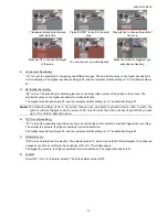
Page 17: ... recording without notice 1 Continuous Recording Icon When the DVR is properly connected with camera you can see the icon recording on the screen 2 Event Recording Icon When the motion alarm detection is activated once motion or external alarm happens you will see the icon motion or external alarm on the screen 3 Timer Recording Icon When the timer record is activated you will see the icon timer o...

Page 18: ...X speed rewind and press twice to get 8X speed etc And the maximum speed is 32X Note During playback the image size of the recording Frame FIELD or CIF will be shown on the screen 2 Pause Image Jog Press PAUSE to pause the playback In the Pause mode Press FF once to get one frame forward Press REW once to get one frame rewind 3 Stop Press STOP under playback mode and the screen will return to live...

Page 19: ...ER to confirm the upgrade 2 Use AP software to remotely upgrade firmware or OSD Step 1 Save the upgrade files at your PC do not change the file name and log into the Video Viewer Step 2 Click Miscellaneous Control to show the miscellaneous control panel In the miscellaneous control panel click Tools on the miscellaneous control panel to enter the upgrade window Step 3 Enter the user name password ...

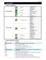
Page 20: ...s Only 5 2 Menu Operation Instruction ITEM FUNCTION QUICK START MENU View change the settings of the quick start menu items MENU Enter exit the quick start menu Make the selection Change the setting Go to the upper layer or sub layer Make the selection ENTER Confirm the password entering ADVANCED MENU In the quick start menu move to and press to enter the advanced setting menu ENTER Go to the sub ...

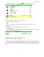
Page 21: ...to and you will see the following screen QUICK START CHANNEL TITLE ON EVENT STATUS ON DATE DISPLAY ON IMAGE SIZE CIF QUALITY BEST IMAGE PER SECOND 100 RECORD TIMER OFF DETECTION TIMER OFF DATE 2008 APR 24 10 20 24 FORMAT Y M D DAYLIGHT SAVING OFF ADVANCE uv SELECT s BACK t NEXT ENTER The submenu items are described below 1 CHANNEL TITLE Select to display the channel title or not ON OFF 2 EVENT STA...

Page 22: ... OFF ADVANCE uv SELECT s BACK t NEXT ENTER The submenu items are described below 1 IMAGE SIZE Select one of the image sizes FRAME FIELD or CIF 2 QUALITY Select one of the 4 quality options BEST HIGH NORMAL and BASIC 3 IMAGE PER SECOND Select the images per second for MANUAL RECORD Take 16CH model as an example NTSC IPS PAL IPS FRAME 15 30 60 120 FRAME 12 25 50 100 FIELD 30 60 120 240 FIELD 25 50 1...

Page 23: ...d below 1 RECORD TIMER Use to change the setting ON OFF When it s set to ON press ENTER to go to its submenu for further settings RECORD TIMER 0 2 4 6 8 10 12 14 16 18 20 22 24 SUN MON TUE WED THU FRI SAT PLEASE CONSULT YOUR INSTALLER FOR ADVANCE SETTINGS uv s t MOVE SELECT X axis 0 24 hours Each time interval within a square is two hours divided into four 30 minutes Y axis Monday Sunday Operation...

Page 24: ...oint marked in yellow color and press MENU to exit Note This function here is only for event record timer setup and activation For motion detection function setup and activation please refer to section 7 1 2 Detection at page 23 6 4 Date In this menu list you can set up the system date and time for this device Note Please DO NOT change the date or time of your DVR after the recording function is a...

Page 25: ...from the following 3 options Y M D M D Y D M Y 3 DAYLIGHT SAVING Use the to specify whether to use daylight saving time ON OFF When it s set to ON press ENTER to go to its submenu for further settings DAYLIGHT SAVING START TIME 4TH SUN MAR 24 00 00 END TIME 4TH SUN OCT 24 00 00 ADJUST 01 00 PLEASE CONSULT YOUR INSTALLER FOR ADVANCE SETTING uv SELECT s BACK t NEXT ENTER Set the start time and end t...

Page 26: ...following screen ADVANCE CONFIG CAMERA DETECTION ALERT NETWORK SNTP DISPLAY RECORD REMOTE PLEASE CONSULT YOUR INSTALLER FOR ADVANCE SETTING uv SELECT s BACK t NEXT ENTER 7 1 1 Camera In this submenu you can make advanced camera settings such as changing the camera title or adjust the brightness Move to CAMERA and press ENTER You will see the following screen CAMERA TITLE BRIG CONT SATU HUE COV REC...

Page 27: ...on In this submenu you can set up detection related functions Move to DETECTION and press ENTER You will see the following screen DETECTION TITLE DET AREA LS SS TS RE ALARM CH1 OFF SETUP 07 03 02 10 OFF CH2 OFF SETUP 07 03 02 10 OFF CH3 OFF SETUP 07 03 02 10 OFF CH4 OFF SETUP 07 03 02 10 OFF CH5 OFF SETUP 07 03 02 10 OFF CH6 OFF SETUP 07 03 02 10 OFF CH7 OFF SETUP 07 03 02 10 OFF CH8 OFF SETUP 07 ...

Page 28: ...he lowest sensitivity setting is 15 The default setting is 03 Note The default setting of SS is 03 which means once an object is detected more than 3 grids the system will get triggered So the value of SS must be less than the number of grids that you set up for the motion detection area 6 TS Time of Sensitivity TS is to set the sensitivity regarding how long one object stays in the detection area...

Page 29: ...ON BUZZER and ALARM BUZZER Note When this item is set to OFF item 3 to item 6 will be disabled even though they are set to ON 3 KEY BUZZER Select to enable or disable the sound when pressing the buttons on the front panel ON OFF 4 VLOSS BUZZER Select to enable or disable the sound when video loss happened ON OFF 5 MOTION BUZZER Select to enable or disable the sound when any motion alarm is trigger...

Page 30: ...SP Internet Service Provider 4 PORT The valid number ranges from 1 to 9999 The default value is 80 Typically the TCP port used by HTTP is 80 However in some cases it is better to change this port number for added flexibility or security See the example below STATIC NETWORK TYPE STATIC IP 192 168 001 080 GATEWAY 192 168 001 080 NETMASK 255 255 255 000 PRIMARY DNS 168 095 001 001 SECONDARY DNS 139 1...

Page 31: ...Y DNS SECONDARY DNS Key in the IP address of the domain name server obtained from your ISP Internet Service Provider 3 PORT The valid number ranges from 1 to 9999 The default value is 80 Typically the TCP port used by HTTP is 80 However in some cases it is better to change this port number for added flexibility or security See the example below DHCP NETWORK TYPE DHCP IP 000 000 000 000 GATEWAY 000...

Page 32: ... of display Move to DISPLAY and press ENTER to enter the submenu You will the following screen DISPLAY DE INTERLACE ON QUAD DWELL DURATION SEC Selected Models Only 03 FULL SCREEN DWELL DURATION SEC 03 VGA OUTPUT 1024 x 768 PLEASE CONSULT YOUR INSTALLER FOR ADVANCE SETTING uv SELECT s BACK t NEXT ENTER The submenu items are described below 1 DE INTERLACE Select to enable or disable the de interlace...

Page 33: ...reen RECORD MANUAL RECORD ENABLE ON EVENT RECORD ENABLE ON TIMER RECORD ENABLE ON EVENT RECORD IPS 100 TIMER RECORD IPS 100 PRE ALARM RECORD ON OVERWRITE ON PLEASE CONSULT YOUR INSTALLER FOR ADVANCE SETTING uv SELECT s BACK t NEXT ENTER The submenu items are described below 1 MANUAL RECORD ENABLE Set the manual recording function on off 2 EVENT RECORD ENABLE Set the event recording function on off...

Page 34: ...0 CH5 CAMERA 000 NORMAL 2400 CH6 CAMERA 000 NORMAL 2400 CH7 CAMERA 000 NORMAL 2400 CH8 CAMERA 000 NORMAL 2400 CH9 CAMERA 000 NORMAL 2400 CH10 CAMERA 000 NORMAL 2400 NEXT PLEASE CONSULT YOUR INSTALLER FOR ADVANCE SETTING uv SELECT s BACK t NEXT ENTER The submenu items are described below 1 TITLE Show the camera title of each channel set in CAMERA 2 DEVICE Select the device type CAMERA PTZ according...

Page 35: ...r NO to cancel 7 UPGRADE For upgrading firmware OSD Before using the USB flash drive please use your PC to format the USB flash drive to FAT32 format first Save the upgrade file in a compatible USB flash drive and insert it into the USB port at the front panel Then press ENTER and select YES to confirm upgrade or NO to cancel Note For the list of compatible USB flash drives please refer to APPENDI...

Page 36: ... FOR ADVANCE SETTING uv SELECT s BACK t NEXT ENTER 7 3 1 Quick Search In this menu list you can search any specific events by time and directly play the file you find Move to QUICK SEARCH and press ENTER You will see a similar screen as the following TIME SEARCH DATE 2008 APR 24 22 48 00 SEARCH HDD ALL HDD START PLEASE CONSULT YOUR INSTALLER FOR ADVANCE SETTING uv SELECT s BACK t NEXT ENTER The su...

Page 37: ... Select the event type MOTION or ALARM 4 SEARCH Change to the HDD you want to search if there are more than one HDD in your DVR by pressing 5 START Move to START and press ENTER to search and directly playback the recorded files 7 3 3 HDD Info In this menu list you can view the remaining capacity of all the connected HDDs in this device Move to HDD INFO and press ENTER You will see a similar scree...

Page 38: ...POWER ON 2008 APR 24 10 23 30 KEY UNLOCK 2008 APR 23 14 37 30 PREV NEXT CLEAN PLEASE CONSULT YOUR INSTALLER FOR ADVANCE SETTING uv SELECT s BACK t NEXT ENTER 7 4 Backup In this menu list you can choose to make a copy for a specified period time to a compatible USB flash drive for your own purpose The backup file can be played directly in your PC via the supplied licensed software Video Viewer or I...

Page 39: ...et the time channel s you want and start USB backup again Move to USB BACKUP and press ENTER You will see a similar screen as the following USB BACKUP START TIME 2008 APR 24 13 00 05 END TIME 2008 APR 24 13 10 05 AVAILABLE SIZE 1960 0MB CHANNEL 01 02 03 04 05 06 07 08 09 10 11 12 13 14 15 16 HDD NUM ALL HDD START PLEASE CONSULT YOUR INSTALLER FOR ADVANCE SETTING uv SELECT s BACK t NEXT ENTER The s...

Page 40: ... and their functions are almost the same as USB BACKUP For the description of the submenu items please refer to the previous page The process below describes how to make a disk backup a Press EJECT to open the disk tray Put the CD or DVD into the DVD writer and press EJECT again to close the disk tray b Go to DISK BACKUP and set the start time end time channels and HDD c Move to START and press EN...

Page 41: ...on nn ne ec ct ti io on n v vi ia a L LA AN N a Connect the DVR to your PC via a RJ 45 network line The default DVR IP address is 192 168 1 10 and the default user name and password are both admin b Set the PC s IP address as 192 168 1 XXX 1 255 except 10 in order to make the PC and DVR under the same domain c Double click icon on your PC desktop to enter the control panel By defaults the Address ...

Page 42: ...h the available IP address es of other DVR s under the same domain as your PC s IP address The found address es will be listed and can be added into the address book by clicking Add into address book For details please see Search at page 42 c Double click the IP address you just added into the address book to log in When you re logged in the Event panel will be shown by defaults 8 1 2 Control Pane...

Page 43: ...VR control panel to operate the DVR remotely For details please see DVR Control at page 59 8 1 3 General Operation Record To record remotely at the same time when any event alarm is triggered at the DVR side click Miscellaneous Control Record Setting to go to the Record Setting page In the Record Setting page you can set the following items Record type Hard disk overwriting Pre post alarm record t...

Page 44: ... be shown at the bottom of the main control panel similar to the following For the playback control panel details please see Playback Screen at page 58 Network Backup Click Miscellaneous Control Backup to go into the Download page as follows and you can select a specific time range or event to make a video backup remotely For details please see Backup at page 43 ...

Page 45: ... this tab with the downloaded video clip is displayed Original Size Click to return to original size of the monitoring view Expand All Views To see all views in the image display area if you have many views and do not want to switch each view by clicking the blue tab described above click to choose a proper split view 1 cut 4 cut 6 cut 9 cut 13 cut 16 cut which best suits your needs The selected v...

Page 46: ...on as needed Remove Select one IP address from the address list and click this button to delete it N A REC When the video viewer is connected to more than one device and not all devices are necessary to enable the manual record function check REC for the connected device s and its manual record function will be on S Se ea ar rc ch h Click to search and view the available IP address es for the DVR ...

Page 47: ...tails Status List Click to view all event and recording logs search the desired log s by date or playback the recording of the selected log For details please refer to Status List at page 57 C Co ol lo or r S Se et tt ti in ng g Click to go into the Color Setting page and you can adjust the brightness contrast hue saturation for a single channel or all channels Choose the desired channel from the ...

Page 48: ...iew the earlier or later logs that are not shown in the current page click Prev Page or Next Page To refresh the event list click Reload File Path Assign the location where the backup files are saved Simultaneous Playback To view the backup images simultaneously when the download process is in progress select Simultaneous Playback You will see the backup images while the images are being downloade...

Page 49: ...24 hours Each time interval within a square is 15 minutes Y axis Monday Sunday Operation You can set the record schedule for 3 record types as needed in this time table 1st timeline Schedule l recording indicated in yellow 2nd timeline Alarm recording indicated in magenta and 3rd timeline Motion recording indicated in cyan Click and hold the start time point and drag to the end time point to set t...

Page 50: ... Select and view the location for saving the recorded video and snapshot pictures To change the saving path for the recorded video clips or snapshots check the drive you want click the cell of Video Path or Picture Path twice and select a new path for saving the video clips or snapshots D Dv vr r S Se et tt ti in ng g Click to view set or modify the DVR setting All the changes you make here will b...

Page 51: ...s when you click one of the buttons in the DVR control panel Log In General Log you can view the system event log s of the connected DVR for reference To check the previous next page if there are more than one page click Prev Page Next Page To refresh the event list click Reload to clear all log s click Clean Account In General Account you can create a new account for login or delete or modify the...

Page 52: ...Record Setting Server Setting X X X Tools X X X Status List Record Snapshot Information Dvr Control X Life Time Select how long this account is allowed to stay online 1 MIN 5 MIN 10 MIN 1 HOUR 1 DAY INFINITE To modify an existing account select the account you want change the setting and click Save To remove an existing account select the account you want and click Delete To save your changes clic...

Page 53: ...bsite which provide free DDNS services and apply a host name DDNS Apply a Go to a website which provide the free DDNS service for example http www dyndns org b Create an account in DynDNS c After creating one account users will receive a confirmation E mail within a few minutes To complete the registration please follow the instructions received Users must complete these steps within 48 hours to c...

Page 54: ...nction is activated the DVR will send an e mail notification to the specified recipients once alarm trigger or motion trigger recording happened Please enable the function of e mail notification in the Alert menu first Mail Notification Function a Add the recipients E mail accounts in Mail Account column Please type the entire E mail address in the Mail from column to ensure E mails will not be bl...

Page 55: ... display etc In Dvr you can see the following items Function Description Host ID Set the host ID from 0 to 254 The default value is 0 System Type Display the current system type NTSC PAL It s automatically detected De interlace Choose to reduce ON or ignore OFF the vibration of the paused picture Daylight Saving Specify whether to use daylight saving time ON OFF If this function is enabled set the...

Page 56: ...her normal camera or PTZ camera ID Set the ID number 0 255 of the connected PTZ camera PROTOCOL Choose NORMAL or P D protocol It is recommended to select PELCO D protocol for the connected PTZ camera of other brands Please choose Normal if it s our own PTZ camera RATE Set the baud rate of each channel 2400 4800 9600 19200 38400 57600 115200 Detection Select the desired channel and click Edit or do...

Page 57: ...tion Apply Return To save the setting click Apply and return to Server Setting window To discard the setting click Return to directly return to Server Setting window without saving Record In Dvr Record you will see the following items for DVR record settings Function Description Image Size Quality Choose the image size FRAME FIELD CIF and quality BEST HIGH NORMAL BASIC Manual Record Event Record T...

Page 58: ...n you want and set how long the beep sound will be lasted Function Description Ext Alert Check this option to enable the external alert Buzzer Enabled This option must be checked for Motion Buzzer Alarm Buzzer Video Loss Buzzer and Key Input Buzzer to take effects Motion Buzzer Alarm Buzzer Video Loss Buzzer Key Input buzzer Check one of these 4 options and you will hear the beep sound when any mo...

Page 59: ...e and Logo Before performing any update finish the following settings first 1 Choose the IP address of the DVR whose firmware needs to be updated from the drop down list or click Search to find 2 Key in the user name password and port number used to access your DVR remotely 3 Select the update option Firmware Language Logo you want For details please see the description below Firmware To upgrade y...

Page 60: ... a graphic file in the BMP format for replacement Note Use the image software to set the image size to 320 240 and save the image as an 8 bit 64 color image in the BMP format b Click Add to locate and select the graphic file The file will be shown in the list If you add the wrong file select it and click Remove c To start updating the logo choose the file from the list and click Update Logo to sta...

Page 61: ...logs set the time range From To and the range unit here Record Type Select the record type you want to search User Alarm Motion RETR Query Click to start sorting the logs specified Delete Delete All Click Delete to remove the selected log s or click Delete All to clear the current log list Tip To select more logs all at once press and hold the Ctrl key on your keyboard and click to select the logs...

Page 62: ...s the detailed playback download information such as the file name record date and time and the speed etc 2 Playback Operation This area is enabled only when the playback is started Rewind Forward Stop Pause Play Rewind Forward Click once to get 2X fast rewind forward twice to get 4X three times to get 8X and four times to get 16X the highest 3 De Interlace Click to reduce the vibration of the pau...

Page 63: ...he 4 quad display modes one by one The 1st view is CH1 CH2 CH5 CH6 the 2nd view is CH3 CH4 CH7 CH8 the 3rd view is CH9 CH10 CH13 CH14 and the 4th view is CH11 CH12 CH15 CH16 When the 4th view is displayed it will start from the 1st view again To exit from this display mode click any other channel display button Note This button is disabled for 4CH DVR model Full Sequence Click to display each chan...

Page 64: ...ent On Off Click it to activate inactivate the network independent function The related buttons will turn to blue Enter Click to confirm the setting or enter your selection R E T R Click to activate the R E T R function R E T R Audio When is selected and activated the R E T R audio function will be on too If you don t want to activate this function click the red icon again to disable this function...

Page 65: ...owing when the login information is correct Note The buttons and functions described below are taking 4CH DVR model as an example NO Function Description 1 Home Click to go to the main page of the DVR 2 Config Click to go to the detailed DVR setting 3 PTZ Click to enter the PTZ mode 4 Channel Selection Click one of the number to switch to the channel you want to see in full screen 5 Selection Clic...

Page 66: ...ewind Forward Click once to get 4X fast rewind forward twice to get 8X three times to get 16X and four times to get 32X the highest Slow Playback Click once to get 4X slow playback and twice to get 8X slow playback 15 Web Transmission H 264 M JPEG QuickTime Depending on the model you have QuickTime is Apple Inc s multimedia software You need to have QuickTime installed in you operation system firs...

Page 67: ...latest QuickTime player c When the download is completed execute the Q Qu ui ic ck kT Ti im me eI In ns st ta al ll le er r e ex xe e file and follow the on screen instructions to finish the installation procedure Step 2 Open your QuickTime player Select File Open URL in New Player and key in the URL address The URL format is rtsp ipaddress portnum live h264 For example rtsp 60 251 8 57 88 live h2...

Page 68: ...riggered the CH15 of the DVR will start alarm triggered recording 10 12 PIN OFF NA 13 EXTERNAL ALARM NO Under the normal operation COM disconnects with NO But when any alarm is triggered COM connects with NO Attention The voltage restriction is under DC24V 1A 14 PIN OFF NA 15 22 ALARM INPUT Connect ALARM INPUT PIN 15 22 and GND PIN 1 connector with wires Once an alarm is triggered the DVR will sta...

Page 69: ...he CH7 of the DVR will start alarm triggered recording 6 12 PIN OFF NA 13 EXTERNAL ALARM NO Under the normal operation COM disconnects with NO But when any alarm is triggered COM connects with NO Attention The voltage restriction is under DC24V 1A 14 PIN OFF NA 15 18 ALARM INPUT Connect ALARM INPUT PIN 15 18 and GND PIN 1 connector with wires Once an alarm is triggered the DVR will start recording...

Page 70: ... the CH3 of the DVR will start alarm triggered recording PIN 6 is Alarm 4 Once the alarm is triggered the CH4 of the DVR will start alarm triggered recording 7 NC Under the normal operation COM connects with NC and disconnects from NO But when any alarm is triggered COM disconnects with NC and connects with NO Attention The voltage restriction is under DC24V 1A 8 NO Under the normal operation COM ...

Page 71: ...750GB Record Time day 25 925 33 78 12 650 48 08 7 520 60 10 BEST 3 445 70 22 25 875 35 71 12 620 50 40 7 475 65 79 HIGH 3 421 74 23 25 865 36 13 12 600 52 08 7 450 69 44 NORMAL 3 400 78 13 25 768 40 69 12 570 54 82 7 440 71 02 FRAME BASIC 3 385 81 17 50 900 34 72 25 800 39 06 12 580 53 88 BEST 7 460 67 93 50 890 35 11 25 780 40 06 12 540 57 87 HIGH 7 450 69 44 50 865 36 13 25 740 42 23 12 460 67 9...

Page 72: ...ll be shown on the screen Note Please use your PC to format the USB flash drive as FAT 32 Note You can backup up to 2GB video data for one time USB backup To backup more data please set the time channel s you want and start USB backup again MANUFACTURER MODEL CAPACITY Apacer AH320 2G AH320A 8G AH220 1G AH320 4G A data RB 18 1G Transcend JFV35 4G JFV30 8G Sony Micro Vault Tiny 1G Sandisk Cruzer Mic...

Page 73: ...CITY ROTATION ST3320613AS 320GB 7200 rpm ST33500320AS 500GB 7200 rpm ST3750330AS 750GB 7200 rpm Seagate ST31000340AS 1000GB 7200 rpm WD3200AAKS 320GB 7200 rpm WD5000AACS 500GB 7200 rpm WD6400AAKS 640GB 7200 rpm WD7500AAKS 750GB 7200 rpm WD WD10EACS 1000GB 7200 rpm STM3500320AS 500GB 7200 rpm Maxtor STM3750330AS 750GB 7200 rpm HDT725032VLA360 320GB 7200 rpm Hitachi HDS721010KLA330 1000GB 7200 rpm ...

Page 74: ...ECORD ENABLE option is set to ON Check the detection function DET is set to ON Motion detection recording is not working Check the detection area AREA has been setup Can t play the recorded data on my DVR There must be at least 8192 images of recorded data for playback to work properly If not your DVR will stop the playback For example if the IPS is set to 30 the recording time should be at least ...

Page 75: ...0x4C L KEY_CH5 0x35 5 KEY_RIGHT 0x52 R KEY_CH6 0x36 6 KEY_POWER 0x57 W KEY_CH7 0x37 7 KEY_REC 0x72 r KEY_CH8 0x38 8 KEY_PLAY 0x50 P KEY_CH9 0x39 9 KEY_SLOW 0x53 S KEY_CH10 0x41 A KEY_ZOOM 0x5A z KEY_CH11 0x42 B KEY_KEY LOCK 0x4B K KEY_CH12 0x43 C KEY_AUDIO 0x64 d KEY_CH13 0x44 D KEY_SEARCH 0x73 S KEY_CH14 0x45 E KEY_PTZ_MODE 0x70 p KEY_CH15 0x46 F KEY_PTZ_PRESET 0x71 q KEY_CH16 0x47 G KEY_PTZ_ZOOM...

Reviews: