background image

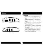
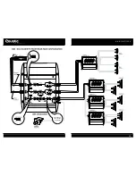
if using the rear outputs from 

the source unit

• Connect the rear line level 

outputs of the source unit to 

the “B” inputs of the crossover.

• Slide the parallel input switch 

to the “OUT” position.

if using the subwoofer outputs 

from the source unit

• Connect the subwoofer line 

level outputs of the source unit 

to the “SUB” inputs of the

crossover.

• Slide the parallel input switch 

to the “OUT” position.

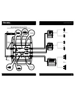
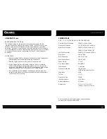
AUDIO OUTPUT AND POWER CONNECTIONS

• Connect the “A”, “B” and sub channel outputs of the XM6 crossover 

to the inputs of their respective amplifiers.

• Connect the crossovers’ B+ terminals to the positive terminal of the vehicle’s

battery. Cut the supplied fuse loop (so there are now two separate wires

that attach to each end of the fuse holder). Install the fuse holder 18" from

the battery on the power wire that runs through firewall or sheet metal to

protect the battery, the vehicle and more importantly, you.

• Connect the GND terminal of the XM6 crossover to the vehicle chassis.

For better conductivity, if necessary, scrape paint off of the chassis to

reveal bare metal at the contact point.

• Connect the REM terminal of the crossover to the remote output

terminal of the source unit to establish crossover remote power on/off

via the source unit. If the source unit does not provide a remote output,

connect to its power antenna terminal.

• Double check all the previous installation steps. If everything is in

order, complete the installation by reconnecting the battery ground to

the vehicle chassis.

WWW.COUSTIC.COM

17

WIRING

Caution:

Routing audio cables and power cables together would invariably

cause radiated engine noise in your audio system. If possible, run audio

cables on one side of your car and power cables on the other. Never route

these wires underneath the vehicle body.

• It is best to route all wires of the audio system along with the existing

electrical wires of the vehicle through this would call for the dismounting

of kick panels, door sills, etc. Where possible, the cleanest and safest

route is under the carpet or behind the side panels.

• If you need to dismantle any part of the vehicle during installation,

make notes of the dismantling process to ensure that you would be

able to reassemble those parts afterwards. All the hardware, for example,

screws, dismantled from the vehicle should be kept in a container to

make reassembly easier.

• Run the various wires accordingly while avoiding sharp edges and

door jams.

• Grommets should be used to protect the wires when they are routed

through bare metal holes. For best protection, we recommend using

automotive flexible plastic tubing and for ease of handling, use plastic

tie-wraps.

• All wires and cables should be “stress relieved” at various points on

both the input and output side of the crossovers. Cable clamps should

be used to reduce stress on the terminals.

Note:

The battery ground should remain 

DISCONNECTED

at all stages 

of installation.

AUDIO INPUT CONNECTIONS

• Connect the front line level 

outputs of the source unit to the

“A” inputs of the crossover.

• If using the XM6 with source unit

that does not have additional 

rear and sub line level outputs,

slide each parallel input switch 

to the “IN” position and skip the

next two steps.

Summary of Contents for XM6

Page 1: ......

Page 2: ...when you sit back and enjoy the high fidelity music Whatever your needs for your ultimate car audio system look to Coustic Car Audio we have the fullest range of car audio components to meet the most critical demands No part of this publication may be reproduced stored in a retrieval system or transmitted in any form or by any means electronically mechanically or otherwise without the prior writte...

Page 3: ...ity of the former to eliminate undesirable peaks and dips in frequency response caused by resonant frequencies present in all enclosed space Since the crossover points can overlap or underlap the resonant frequencies i e asymmetrically Coustic XM6 series allows you to create an acoustically flat and smooth frequency response environment LINE LEVEL INPUTS The XM6 crossover features pre amp inputs f...

Page 4: ...ne Level Inputs Connects to the subwoofer channel RCA outputs of the source unit 7 Bass Drive Remote Sub Gain Control Port Connection for optional R S remote to control subwoofer output levels 8 Subwoofer Line Outputs Connects to the dedicated subwoofer ampli fier left right inputs 9 B Channel Line Outputs Depending on the B channels configuration the crossover s B channel outputs connect to the d...

Page 5: ...band pass frequency range is 40Hz to 3kHz 18dB Octave 16 Subwoofer Frequency Selector For selection of the low pass crossover frequency between 40Hz and 200Hz 36dB Octave 17 Bass Shaper Frequency Selector For selection of low frequency equalization point between 40Hz 100Hz 18 Bass Shaper Boost Level Control For adjusting the Bass Shapers selected equalization frequency level with a maximum boost o...

Page 6: ... carpeted cut out small circles of the carpet and padding around the four mounting holes to expose the metal underneath Use a center punch to ensure drilling the exact position for the screws Drill four 4 1 8 pilot holes DO NOT BEGIN DRILLING UNTIL YOU HAVE PUT THE CROSSOVER ASIDE USING THE CROSSOVER AS A DRILLING GUIDE MAY CAUSE IRREPARABLE DAMAGE TO THE UNIT Mount the XM6 crossover with the Phil...

Page 7: ...WWW COUSTIC COM 13 See Page 20 XM6 Phase Adjustment See Page 20 XM6 Phase Adjustment ...

Page 8: ...WWW COUSTIC COM 15 See Page 20 XM6 Phase Adjustment ...

Page 9: ...IC COM 17 WIRING Caution Routing audio cables and power cables together would invariably cause radiated engine noise in your audio system If possible run audio cables on one side of your car and power cables on the other Never route these wires underneath the vehicle body It is best to route all wires of the audio system along with the existing electrical wires of the vehicle through this would ca...

Page 10: ...ality you can choose any of the frequencies between the lowest and the highest setting marked on the selectors When setting the crossover frequencies it is best to use compact discs or cassette tapes with greater dynamic range Center the tone balance and fader controls of the source unit leaving the other controls at their previous positions Set the volume of the source unit to approximately 2 3 o...

Page 11: ...ld be either an uneven stereo balance loss of midrange or midbass almost no bass or the bass seems to lag behind the highs commonly known as out of phase If this is the case experiment with the phase inverter switch for a position that gives you an even stereo balance more midrange or midbass and more bass output from the subwoofer music is undefined and may lose low frequesncy response music is p...

Page 12: ...re will vary depending upon the low frequency response of the vehicles interior Set the Boost control half way between 0dB and 18dB Starting from the preset frequency gradually adjust the Frequency control downward or upward until you get a smooth even bass response Once the frequency has been chosen you may increase or decrease the equalization by adjusting the Boost control upward or downward NO...

Page 13: ... apply For additional information call us at 602 438 2020 or visit our website at www coustic com WWW COUSTIC COM 25 TROUBLESHOOTING GUIDE SYMPTOM No Power PROBABLE CAUSE Check all the ground B and remote terminals for tight connection Check all fuses Use a Volt Ohm meter to check all power wire connections to see if the system is receiving 12VDC SYMPTOM Motorboating The power indicator going off ...

Page 14: ...WWW COUSTIC COM 27 NOTES ...

Page 15: ...M146 m ...

Reviews: