Samson S Class, Owner'S Manual
The Samson S Class Owner's Manual is a comprehensive guide to understanding and operating your Samson S Class product. Easily download the manual for free from our website to ensure you get the most out of your device. Get all the information you need at your fingertips to enhance your user experience.
Share
Download


Reviews:
No comments
Related manuals for S Class
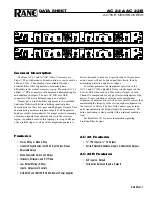
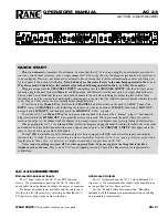
AC 22
Brand: Rane Pages: 4
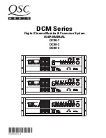
DCM-1
Brand: QSC Pages: 36
AD 22B
Brand: Rane Pages: 6
AC 23
Brand: Rane Pages: 18

XM6
Brand: Coustic Pages: 15
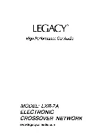
LXR-7A
Brand: Legacy Pages: 12
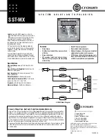
SST-MX
Brand: Crown Pages: 1
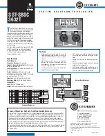
SST-SBSC 3632T
Brand: Crown Pages: 1
F.A.C.T. F-3
Brand: XETEC Pages: 6
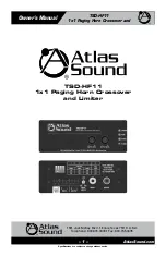
TSD-HF11
Brand: Atlas Pages: 16
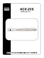
ACX-23S
Brand: DAPAudio Pages: 13
HFEQ
Brand: Hifonics Pages: 10
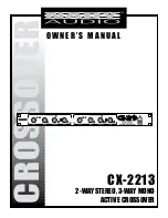
CX-2213
Brand: Nady Audio Pages: 10
SNAXO 362BMR
Brand: NAIM Pages: 24
KLIMAX AKTIV
Brand: Linn Pages: 23
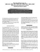
XM16L-3KK
Brand: Marchand Electronics Pages: 12
FDS 310
Brand: BSS Audio Pages: 40
SUPER-X PRO CX2310
Brand: Behringer Pages: 13


