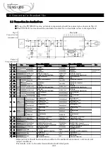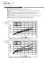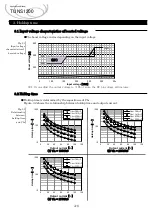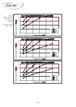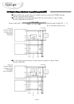
Fig.1.1
Pin Assignment
Table 1.1
Pin configuration
and function
1.1 Pin Assignment
⑩
⑪
-DC output
Remote sensing(-)
Remote s)
Current balance
A-1
RC2
PGG
ITRM
VTRM
AUX
AC2
R
+BC
-BC
+VOUT
-VOUT
+S
-S
CB
-
Mounting hole(FG)
Remote ON/OFF
Alarm
②
RC1
PG
FG
⑫
⑬
⑭
⑮
⑯
⑰
⑲
No.
①
Function
AC input
External resistor for inrush current protection
+BC output
-BC output
+DC output
③
④
⑤
⑥⑦
⑧⑨
Pin
Connection
AC1
Remote ON/OFF ground
Alarm ground
Adjustment of output current
Adjustment of output voltage
Auxiliary output for remote ON/OFF
⑱
Applications Manual
TUNS1200
2.1 Pin configuration
1. Pin Assignment
-VOUT
+VOUT
③
R
⑭
PGG
⑲
PG
⑬
RC2
⑱
RC1
⑫
CB
⑰
AUX
⑪
-S
⑯
VTRM
⑩
+S
⑮
ITRM
①
AC1
②
AC2
④
+BC
⑤
-BC
⑨
⑧
⑦
⑥
Bottom view
4-FG


