■
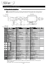
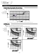
The boost voltage varies depending on the input voltage.
Fig.3.1
Input voltage
characteristics of
boosted voltage
※1:If you adjust the output voltage to +10% or more, the BC pin voltage will increase.
■
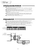
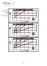
Holdup time is determined by the capacitance of Cbc.
Figure 3.2 shows the relationship between holdup time and output current.
Fig.3.2
Relationship
between
holdup time
and Cbc
3.1 Input voltage characteristics of boosted voltage
3.2 Holdup time
A-8
Applications Manual
TUNS1200
300
350
400
450
50
100
150
200
250
300
350
B
oos
t
v
olta
ge
[
V
]
Input voltage
[
VAC
]
(
※
1)
(365V)
(395V)
(430V)
2.1 Pin configuration
3. Holdup time
10
100
1000
0
20
40
60
80
100
120
Hold
up
tim
e
[
ms
]
Output current
[
%
]
Cbc=780
μ
F
Cbc=1410
μ
F
Cbc=2350
μ
F
Cbc=3290
μ
F
10
100
1000
0
20
40
60
80
100
120
Hold
up
tim
e
[
ms
]
Output current
[
%
]
Cbc=780
μ
F
Cbc=1410
μ
F
Cbc=2350
μ
F
Cbc=3290
μ
F
10
100
1000
0
20
40
60
80
100
120
Hold
up
tim
e
[
ms
]
Output current
[
%
]
Cbc=780
μ
F
Cbc=1410
μ
F
Cbc=2350
μ
F
(1) Vin = 100VAC
(2) Vin = 200VAC
(3) Vin = 277VAC

