


■
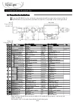
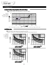
By using PG, it is possible to monitor power supply whether normal operation or
abnormal operation. The PG signal is "Low" when the power supply operates correctly.
The signal turns to "High" when the power supply stops.
■
The PG signal sequence is shown in Fig6.1.
Fig6.1
PG signal
sequence
※
1
V1
:
60% of the set output voltage
※
2
V2
:
20% of the rated output voltage
※
1
V1
:
60% of the set output voltage
※
2
V2
:
20% of the rated output voltage
6.1 Power Good
A-16
Applications Manual
TUNS1200
AC Input
voltage
Output
voltage
Remote
ON/OFF
ACin
RC
RC
RC
RC
ON
OFF ON
OFF ON
PG
AUX
O V P
O T P
O v e r C u r r e n t
s t a t e
OVP
OTP
OCP
Hi-cup
V1
※
1
12V typ
0V
Low
High
ON
OFF
0V
0V
V2
※
2
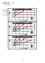
AC Input
voltage
Output
voltage
Remote
ON/OFF
A d j u s t a b l e
Constant
Current
OFF
PG
AUX
RC
ON
A d j u s t a b l e
Voltage
ACin
ACin
ON
RC
OFF
V1
※
1
12V typ
0V
Low
High
ON
OFF
0V
0V
V2
※
2
CC
-control
CV
-control
2.1
Pin configuration
6. Other functions