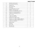
Cosco Fitness SX-1122 Manual Download Page 6


- 6 -

PART LIST 

PART  NO 

PART  NAME 

Q'TY 

1 Motor 

cover 


Front roller with fly wheel   

3 Rear 

roller 


4 Running 

belt 


s

hock-absorbing of roller   

6 Running 

deck 


7 Motor 

belt 


8 Motor 


Speed sensor frame   

10 Speed 

sensor 


11 Frame 

of 

motor 


12 Side 

rail 


13 

Rectangle plug tube     

14 

Control board of motor   

15 Transformer 


16 Power 

wire 


17 Power 

wire 

cushion 


18 

Fuse   

19 Power 

key 


20 

Adjust cap of motor   

21 Running 

platform 


22 

Ferric block of side rail   

23 

Rubber washer of running deck   

24 

Side rail cushion   

25 

Supportive tube of running deck   

26 End 

cap 


27 Manual 

incline 


28 Deck 

frame 

localizer 


29 Torsion 

spring 


30 

Deck frame support board   

31 Motor 

belly 

pan 


32 

Move wheel of base frame   

33 Rubber 

washer 


34 Damper 


35 Base 

frame 


36 Level 

frame 


Summary of Contents for SX-1122

Page 1: ...TREADMILL MANUAL SX 1122...

Page 2: ...itness equipment Do some warm up exercise before use you ll get twice the result with half the effort Such as follows extend the neck up and down twist the waist left and right level push forwards upr...

Page 3: ...l clear 3 The treadmill running mat will not stop immediately if any object becomes caught in the mat or rollers IN EMERGENCY Pull the safety key cord to remove safety key 4 Always check the treadmill...

Page 4: ...should be taken when mounting and dismounting the unit 15 Do not place any liquids on any part of the treadmill 16 To prevent shock keep all electric components such as the motor cord and switch away...

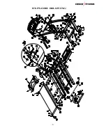
Page 5: ...5 EXPLORE DRAWING...

Page 6: ...ol board of motor 1 15 Transformer 1 16 Power wire 1 17 Power wire cushion 1 18 Fuse 1 19 Power key 1 20 Adjust cap of motor 1 21 Running platform 1 22 Ferric block of side rail 2 23 Rubber washer of...

Page 7: ...t 2 52 6 washer 8 53 M6 Nylon nut 8 54 5 32 Bolt 2 55 5 32 no slip washer 2 56 ST2 9 8 Screw 2 57 M8 35mm Allen head bolt 1 58 M8 Nylon nut 1 59 M8 20mm Allen head bolt 4 60 8 spring washer 6 61 M8 65...

Page 8: ...cut key 1 83 Outside wire of SPEED SPEED key 1 84 Connect wire of handlebar pulse wire 2 85 ST2 3 6 Screw 4 86 Control wire of upright 1 87 Control wire of computer 1 88 Outside wire of computer of pu...

Page 9: ...n n o C 7 3 2 r e h s a W 8 8 4 2 t l o b d a e h n e l l A m m 0 4 8 M 8 6 2 t l o b d a e h n e l l A m m 0 2 8 M 9 6 4 r e h s a w 0 1 0 7 2 t l o b d a e h n e l l A m m 5 3 0 1 M 1 7 4 t l o b d...

Page 10: ...e You should unscrewing the M10 20 Allen head bolt as above picture before assembling STEP1 Then fix the Running platform on the base frame with M10 35mm Allen head bolt 71 and Connect sleeve of runni...

Page 11: ...he control wire of base frame 91 2 Then fix the uprights on the base frame with M10 20mm Allen head bolt 73 and 10 washer 70 M8 40mm Allen head bolt 68 and 8 Washer 48 STEP3 1 Connect the cross brace...

Page 12: ...pulse Control wire of upright 86 and Control wire of computer 87 Outside wire of SPEED SPEED key 83 and Outside wire of computer of SPEED SPEED key 89 Connect wire of handlebar pulse wire 84 and Outsi...

Page 13: ...Strike the damper 2 Hold on to the top end covers as shown by the arrow on top left and pull down the treadmill slowly on the ground and fix the knob nut To fold up the treadmill To fold up treadmill...

Page 14: ...key the MANUAL LED will bright and the time window will flash Press SPEED SPEED key to adjust the setting value Press START key the motor will run after the countdown of 3 seconds The initial speed i...

Page 15: ...PROG1 PROG2 PROG3 PROG4 PROG5 PROG6 be displayed in turn Press MODE key all the setting value will be cleared it will display a initial value and flash in the setting window SPEED In the running stat...

Page 16: ...ed The Display Range The initial data during Normal Mode The initial data of Count Down Mode The range of data during Count Down Mode The Range of the Data TIME mm ss 0 00 20 00 8 00 99 00 Every time1...

Page 17: ...n panel and controller Check that the lines between panel and controller are connected or not Replace the connection lines Replace the device Replace the panel Replace the adapter Er2 Error on motor M...

Page 18: ...urge protector Using the hex key provided turn the left rear roller adjustment bolt 1 4 turn in the clockwise direction Plug the power cord back into the surge protector and run the treadmill at 2 5 m...

Page 19: ...8300 available at most stores TO APPLY LUBRICANT TO THE WALKING BELT 1 Position the walking belt so that the seam is located on top and in center of the walking board 2 Insert the spray nozzle into th...

Reviews: