background image

Page  4

SRP 003-304 • Issue 9 • July 2004

7.

Installing Holes

IMPORTANT: 

Remove the base plate from the

housing before cutting any holes.

7.1

Determine the size hole needed based on

the fitting being used. Measure and mark the
location of the hole centers, based on
dimensions in Figure 3, on the bottom of the
unit. The 2-inch conduit holes are represented
by the larger circles and the 1-inch conduit
holes by the smaller circles.

7.2

Cut holes as required for your coupling

fitting. Follow local safety practices.

7.3

Install the fittings (purchased separately).

Fitting kits are available in three types. The kit
is dependant on the type of fitting desired for
your application.

7.4

Reinstall the base plate.

8.

Mounting

NOTE: 

If you will be mounting the EDC without

the stabilizer bracket, remove and discard the
stabilizer bracket. Rotate the top bracket so the
elliptical hole is exposed. Position the housing as
desired and secure using 

1

/

4

-inch screws in the top

and bottom brackets.

8.1 When wall-mounting,

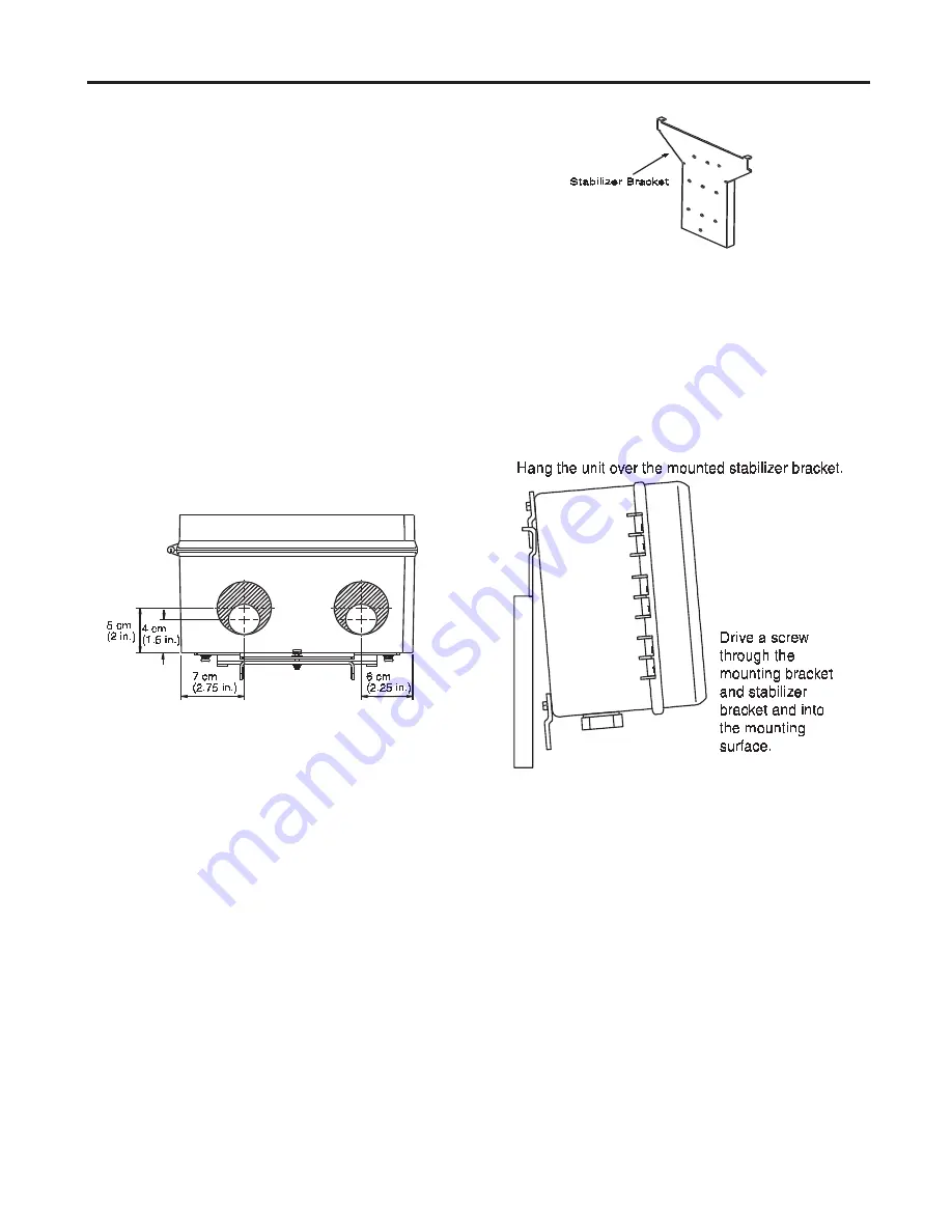
a) Remove the stabilizer bracket (Figure 4).

b) Drive 

1

/

4

-inch screws or wall anchors

through the stabilizer bracket and into the
mounting surface. 

Do not install a screw in the

bottom hole of the stabilizer bracket at this time.

c) Hang the unit on the stabilizer bracket,

ensuring that the top mounting bracket is
resting between the two tabs on the
stabilizer bracket (Figure 5).

8.2 When the EDC will be mounted onto a
utility pole:

a) Secure the stabilizer bracket to the pole

using 

  1

/

4

 -inch screws. 

Do not install a screw

into the bottom bracket at this time.

b) Hang the EDC on the stabilizer bracket,

ensuring that the top mounting bracket is
resting between the two tabs on the
stabilizer bracket.

c) Line up the elliptical hole in the bottom

mounting bracket with the bottom hole in
the stabilizer bracket. Drive a 

1

/

4

-inch screw

through the brackets and into the utility
pole.

d) Mounting hardware is not provided.

Figure 3

Figure 4

Figure 5

d) Align the elliptical hole in the bottom

mounting bracket and the bottom hole in
the stabilizer bracket. Install a 

1

/

4

-in. screw

through the holes into the mounting
surface.

e) Mounting hardware is not provided.

Summary of Contents for EDC-02P-NH

Page 1: ...ctions NOTE Read and understand this procedure as well as the instructions provided with related assemblies before beginning an installation Make sure you know how the unit will be mounted and how the distribution cable and drop cable will be routed to the unit 2 Description 2 1 The EDC is a cabinet designed for storage and protection of fiber optic connections and splices in an outdoor environmen...

Page 2: ...micals and cutting fiber Pieces of glass fiber are very sharp and can damage the cornea easily CAUTION The wearing of safety gloves to protect hands from accidental injury is strongly recommended when using sharp instruments CAUTION Isopropyl alcohol is flammable with a flashpoint at 50 F It can cause irritation to eyes on contact In case of eye contact flush eyes with water for at least 15 minute...

Page 3: ...x wrench Utility pole or wall mounting hardware as required by your installation Two cable entry port fittings ordered separately and sealant if required 5 Components 5 1 Components are illustrated in Figure 2 The base plate is the dark metal plate that holds the components inside the enclosure It is secured by four screws 5 2 An installation kit is provided that includes cable ties central member...

Page 4: ...ets 8 1 When wall mounting a Remove the stabilizer bracket Figure 4 b Drive 1 4 inch screws or wall anchors through the stabilizer bracket and into the mounting surface Do not install a screw in the bottom hole of the stabilizer bracket at this time c Hang the unit on the stabilizer bracket ensuring that the top mounting bracket is resting between the two tabs on the stabilizer bracket Figure 5 8 ...

Page 5: ...on the left at the base of the unit 9 2 Perform cable sheath removal steps per instructions for the type of cable being installed Cut the cable to 2 meters 6 feet inside the unit NOTE Do not expose the bare fiber until you are ready to terminate it 9 3 Install a sheath retention clamp onto the cable sheath as illustrated in Figure 6 If an armored cable is used install the ground clamp before insta...

Page 6: ... nut c Insert the central member of the cable between the bracket and the U shaped washer d Arrange the buffer tubes to ensure clearance around the central member clamp assembly and hardware e Tighten the hex nut f Install the two flat washers g Loosely install the other hex nut h Wrap the strength member yarn in a clockwise direction around the bolt and between the flat washers i Tighten the seco...

Page 7: ...he connector panels into the connector support bracket Figure 14 10 Connector Panels 10 1 LANscape connector panels Figure 12 are sold separately typically with connector adapters installed 10 2 If fibers are not already connectorized install connectors onto the fibers using pigtail splicing or direct connectorization per manufacturer s instructions If installing BTF kits proceed to Section 12 10 ...

Page 8: ...ons provided with the splice trays to determine the appropriate length of fiber required in the tray Measure from the first mark towards the end of the cable and mark the cable This is the fiber that will be routed inside the splice tray f Trim the excess buffer tube beyond the second mark g Remove the splice tray and the coiled buffer tubes h Strip the buffer tube from the fibers from the mark yo...

Page 9: ...ius to the connector panel 11 7 Secure the splice tray to the wall as shown in Figure 18 Discard spacers as required for the type of tray installed 12 Installing BTF Kits 12 1 Fiber optic cable can be installed using Corning Cable Systems BTF kits 12 2 Route the buffer tubes twice around the radius guides in a counterclockwise direction Mark the location of the mounting bracket on the buffer tubes...

Page 10: ...ius guides 13 2 If the drop cables do not include central members secure the cables to the bracket using a loosely tightened cable tie When central member strain relief is necessary remove the drop cable strain relief bracket and secure the cable to the bracket using a cable tie as shown Figure 22 a Install the 8 32x5 8 screw from the front side of the strain relief bracket through the flat washer...

Page 11: ... fiber optic cable to make sure bends do not exceed the minimum bend radius Check cable for unnecessary strain Check cable entries and exits for crimping or crushing Documentation Check record label to make sure it is clear and accurate 15 Specifications The unit weighs 4 3 kg 10 lb f Trim off the excess yarn and central member g Reinstall the strain relief bracket NOTE The exposed length of the c...

Page 12: ...s are the properties of their respective owners Corning Cable Systems is ISO 9001 certified 2000 2004 Corning Cable Systems All rights reserved Published in the USA p n 003 304 July 2004 Customer Service and Information Telephone Customer Service US or Canada 1 800 743 2671 International 1 828 901 5000 Fax 1 828 325 5060 Correspondence Corning Cable Systems LLC PO Box 489 Hickory NC 28603 0489 USA...

Reviews: