Installation of MN4100
This installation procedure assumes that
mechanical mounting and positioning has
already occurred, for specific mounting
instructions relating to CDX8900-470, please
view the MN4100 Mounting Arm Installation
Manual.
A typical industrial installation will comprise
of armoured cable for both power and
communications, terminating in a junction box
adjacent to the camera. Unarmoured power
and communications cables are run from the
junction box to the camera via the two M16
compression gland entries located in the
camera base.
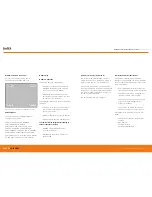
Typical camera installation diagram
1
Remove rear weather cap from camera to expose
Ethernet socket and power terminals.
2
Insert power and communications cables into camera
via 2xM16 compression glands provided. NOTE, these
glands will accept cables with outside diameters from
3mm – 7mm.
3
Connect 11-30VDC to the green power connector
(provided) and attached to Chassis. There are three
connections
Top:
0V
Centre:
Supplemental GND*
Bottom:
+ve
*GND is a supplemental Ground connection. MN4000 Primary
Ground is via the RJ45 socket and communications line. If no
communications are installed, the Supplemental GND may
be connected in accordance with local Electrical Codes /
Regulatory Requirements.
4
Attached an RJ45 plug to the communications cable.
DO NOT PLUG INTO THE CAMERA AT THIS STAGE
.
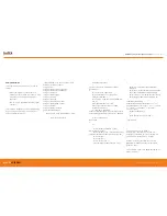
Power connector
RJ45 Socket
Compression glands
RUGGED
AUTHORITY
MONITIR Series Thermal Imaging Cameras
– User Manual
13
Document Reference MONITIRSERIESUM Rev. A


