Continental Hydraulics CEM-PA-B Installation Manual Download Page 12


Continental Hydraulics Installation Manual 


Page 12 of 24 

CEM-PA-B 

CHI 1020688     01/2016 

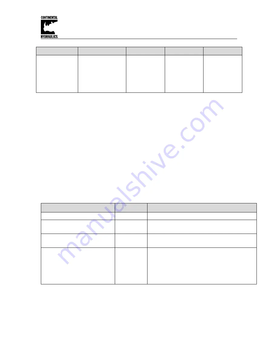
AINMODE - Analogue input scaling parameters 

Command


Parameters


Unit


Group


FUNCTION 

AIN:I 

a b c x


i = A|B 

a= -10000… 10000 

b= -10000… 10000 

c= -10000… 10000 

x

= V|C  

0.01% 

EXP


AA 

A-B 

This command offers an individual scalable input. The following linear equation is used for the 
scaling. 

Output = A/B ∙ (Input – C) 

The 

“C” value 

is the offset (e.g. 

to compensate the 4 mA in case of a 4… 20 mA input signal).  

The variables 

A

 and 

are defining the gain factor with which the signal range is scaled up to  

100 % (e.g. 1.25 if using 4… 20mA input signal, defined in default current settings by A = 1250 
and B = 1000). The internal shunt for the current input signal is activated when parameters AIN:A 
and AIN:B are set to Current (X=C). 

The gain factor is calculated by dividing total input signal range (

A

) by the actual input range (

B

). 

In the case of a 4-20mA with a single solenoid valve, the total range is 0-20mA, which means 

A=20

. The actual range is 4-20 mA, therefore, 

B= (20-4) =16

. An offset, 

C

, must be added to 

compensate for the 0-4mA not being used of the full range. The offset is 4mA/20mA=0.2 or 20%. 
Therefore 

C=2000

 since the unit value for 

C

 is 0.01%. 

Shown in the below table are the most common input command signal and the corresponding 
settings to be used. 


Typical settings (examples): 

Command


Input


Description


AIN:X   1000   1000      0 V 

0… 10 V 

Range: 0… 100 % 

AIN:X     10      8   1000 V OR 

AIN:X   1000    800   1000 V 

1… 9 V 

Range: 0… 100 %; 1 V = 1000 used for the offset and 
gained by 10 / 8 (10 V divided by 8 V (9 V -1 V)) 

AIN:X     10      4    500 V OR 

AIN:X   1000    400    500 V 

0.5… 4.5 V 

Range: 0… 100 %; 0.5 V = 500 used for the offset and 
gained by 10 / 4 (10 V divided by 4 V (4.5 V -0.5 V)) 

AIN:X     20     16   2000 C


OR 

AIN:X   2000   1600   2000 C OR 

AIN:X   1250   1000   2000 C 

4… 20mA


Range: 0… 100 % 

The offset will be compensated on 20 % (4 mA) and the 
signal (16 mA = 20 mA 

– 4 mA) will be gained to 100 %  

(20 mA). 

Each of this parameterization for 4… 20 mA is setting the 
range to 0… 100 %. 


Summary of Contents for CEM-PA-B

Page 1: ...system requirements Input command can be ramped PID variables are adjustable over a wide range The Amplifier is easily switched from open loop to closed loop control Min and Max output current are ad...

Page 2: ...Diagram 6 LED Definitions 7 Terminal Identification 7 Parameter List 8 Command Parameter Descriptions LG Language 9 MODE 9 SENS 9 EOUT 10 SYS_RANGE 10 SIGNAL X SIGNAL W 10 AINMODE Signal Scaling mode...

Page 3: ...0 390 Ohm Signal resolution 0 006 incl Oversampling PWM output A 0 5 to 2 6 Amp broken wire and short circuit monitored PWM frequency Hz 61 2604 Sample time pressure control ms 1 Sample time solenoid...

Page 4: ...the GUI program 6 Open the Options Tab and verify that the correct com port full Duplex and 57 6K Baud rates are selected 7 Connect with the CEM by selecting the connect button 8 Click on the ID Butt...

Page 5: ...no need for shielding on these power conductors Wire size is chosen to provide an acceptable voltage drop between the module and the valve solenoid The following chart is based on 5 drop for 12v and 2...

Page 6: ...Continental Hydraulics Installation Manual Page 6 of 24 CEM PA B CHI 1020688 01 2016 Circuit Diagram...

Page 7: ...ers are inconsistent To acknowledge the error data has to be saved with the SAVE command or the corresponding button in the CHI PC GREEN GREEN YELLOW A Terminal Identification Input and output signals...

Page 8: ...14 RA DOWN 100 Command signal ramp time ms X X 15 C P 50 P gain x 0 01 x X 15 C I 4000 I gain 0 01ms X X 15 C D 0 D gain 0 1ms X X 15 C D_T1 500 D gain filter 0 1ms x X 15 C FF 8000 Feed forward 0 01...

Page 9: ...have a more significant influence on system behavior and should accordingly be changed with care SENS Malfunction monitor Command Parameters Unit Group SENS x x ON OFF AUTO STD This command is used to...

Page 10: ...parameter set The effects should be analyzed by the user for each application from the point of view of safety SYS_RANGE System pressure Command Parameters Unit Group SYS_RANGE X x 10 1000 bar STD Th...

Page 11: ...nput signal being used are not as listed the AINMODE is available in the MATH mode where the input signals can be scaled by a linear equation To enter the MATH option you must change the AINMODE to MA...

Page 12: ...e B In the case of a 4 20mA with a single solenoid valve the total range is 0 20mA which means A 20 The actual range is 4 20 mA therefore B 20 4 16 An offset C must be added to compensate for the 0 4m...

Page 13: ...justment of the zero point of the sensor If the command signal and feedback signals are not zeroed to each other this offset should be used Using of the commands SYS_RANGE N_RANGE X and OFFSET X Examp...

Page 14: ...ge 14 of 24 CEM PA B CHI 1020688 01 2016 RA Command signal ramp time Command Parameter Unit Group RA I X i UP DOWN x 1 600000 ms STD Two quadrant ramp function The ramp time is separately set for UP a...

Page 15: ...10000 0 01 0 1 ms 0 1 ms 0 1 ms 0 01 STD The control function will be parameterized via this command The C P I and D gain are similar to a standard PID controller The T1 factor is used for the D gain...

Page 16: ...olled by this command C I_LIM Limitation of the integrator range faster control function by reduced pressure overshoots By a high nonlinearity of the valve the LIM value must be sufficient to compensa...

Page 17: ...ith the MIN value the overlap dead band of the valve will be compensated Via the TRIGGER the activation point of the MIN function is set and so a non sensitive range around the zero point1 can be spec...

Page 18: ...the nominal output current3 see CURRENT command The dither frequency is defined in Hz Depending on the internal calculations the frequency is adjustable in steps only4 The PPWM and IPWM parameters in...

Page 19: ...z The optimum frequency depends on the valve If the PWM frequency is less than 500 Hz the dither amplitude DAMPL should be set to zero The PPWM and IPWM parameters should be adapted when using low PWM...

Page 20: ...adjustments are done automatically If the PWM frequency is 250 Hz the dynamic of the current controller has to be decreased Typical values are PPWM 1 3 and IPWM 40 80 If the PWM frequency is 1000 Hz t...

Page 21: ...0 mA Out of range or broken wire The output will be switched off Feedback signal PIN 14 4 20 mA Out of range or broken wire The output will be switched off Solenoids on PIN 3 4 Wrong cabling broken wi...

Page 22: ...ENABLE is active the READY LED is active no current to the solenoid no pressure build up To locate errors in the pressure control circuit it is useful to start with the open loop pressure control PIN...

Page 23: ...to 0 disabled 7 ENABLE and START PIN 6 are active READY LED is ON the pressure control works but the pressure is not equal to the command input The system works generally but wrong control loop settin...

Page 24: ...margin 3 The integrator time constant C I fixes the static error Typical values are 100 ms to 1200 ms Optimize this parameter by monitoring the transient response ENABLE and START PIN6 are active the...

Reviews: