3. Each Component Function
IPC-PT/MV10 / IPC-PT/LS10 / HPC-HMV10 / HPC-HLS10 Hardware Manual
15
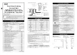
COM2 RS-422A/RS-485 data transmission mode setting
The data transmission mode setting switch (SW4) can be used to switch between half-duplex and
full-duplex and between RTS and CTS in full-duplex mode. Set the appropriate data transmission
mode depending on the remote device to which to connect this board.
Set the transmission mode using from the bit 6 to bit 8.
Setting procedure
Table 3.6. Data transmission mode setting
Full duplex [Full]
Half duplex [Half]
RTS/CTS self-loop
RTS/CTS connection to
remote device
Setting
procedure
(SW4)
1 2 3 4 5 6 7 8
ON
1 2 3 4 5 6 7 8
ON
1 2 3 4 5 6 7 8
ON
Description
Only TxD is enabled as a
data line. The
transmission or reception
mode can be selected by
the RTS signal from this
board.
If the connected device has
no RTS and CTS signals, the
CTS signal becomes active by
making the RTS signal of
this board active.
Used with the unit connected
to the RTS and CTS signals
of the connected device
CAUTION
Do not set bits 7 and 8 of each switch to both ON. Doing so may cause the board to malfunction.
Connection Procedure
COM2
TX_enable
TXD
RXD
RX_enable
TXD+ 4
TXD- 5
RXD+ 8
RXD- 9
Figure 3.4. Full-Duplex Connection Method
COM2
TX_enable
TXD
RXD
RX_enable
TXD+ 4
TXD- 5
RXD+ 8
RXD- 9
Figure 3.5. Half-Duplex Connection Method


